Image forming method and optical coherence tomograph apparatus using optical coherence tomography

a tomograph and optical coherence technology, applied in the field of image forming methods and optical coherence tomograph apparatuses, can solve the problems of difficult to increase the lateral resolution of the tomograph image in an sd-, and the likelihood of a large shift in data distance in the depth direction, so as to achieve the effect of increasing the lateral resolution

Active Publication Date: 2010-07-01
FIFTH THIRD BANK +1
View PDF13 Cites 88 Cited by
  • Summary
  • Abstract
  • Description
  • Claims
  • Application Information

AI Technical Summary

Benefits of technology

[0016]It is pointed out typically that there is a difficulty in increasing a lateral resolution of a tomography image in an SD-OCT (a lateral resolution is a resol...

Problems solved by technology

It is pointed out typically that there is a difficulty in increasing a lateral resolution of a tomography image in an SD-OCT (a lateral resolution is a resolution with respect to an image in an in-plane direction in each depth position against a depth direction of an inspection object being called a lon...

Method used


Image

  • Image forming method and optical coherence tomograph apparatus using optical coherence tomography
  • Image forming method and optical coherence tomograph apparatus using optical coherence tomography
  • Image forming method and optical coherence tomograph apparatus using optical coherence tomography

Examples


first embodiment

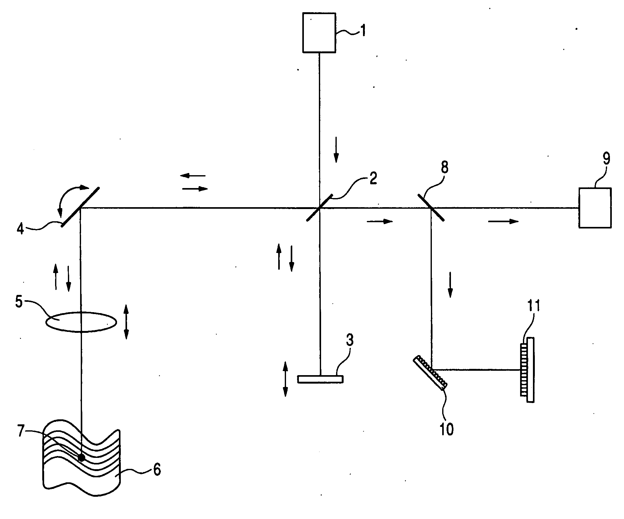
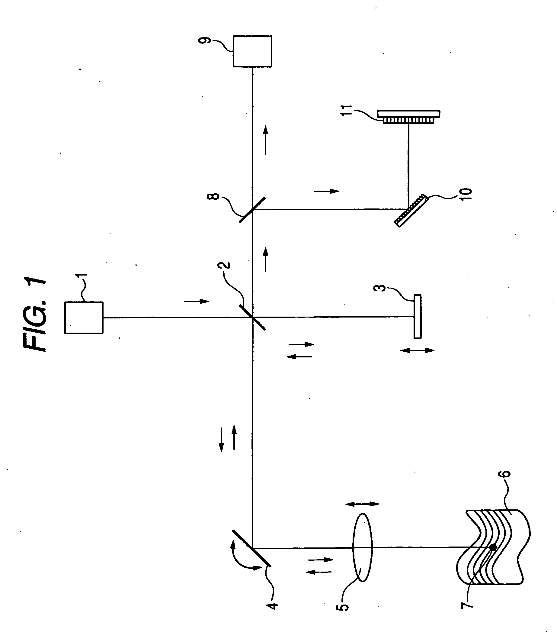
[0109]An image forming method using an optical coherence tomography (in other words, an optical coherent tomographic method) which relates to a first embodiment has at least the following steps 1 to 4.

[0110]1. A first image information obtaining step of obtaining first image information (a one-dimensional, two-dimensional, or three-dimensional image) of an inspection object at a position including a first focus with respect to an optical axis direction which is a direction in which light is directed onto the inspection object

[0111]2. A second image information obtaining step of obtaining second image information (a one-dimensional, two-dimensional, or three-dimensional image) of the inspection object at a position including a second focus different from the first focus with respect to the optical axis direction

[0112]3. A step of obtaining third image information, which is tomography image information of the inspection object and includes a tomography image of the inspection object a...

second embodiment

Correction of SD-OCT Image with SD-OCT Image

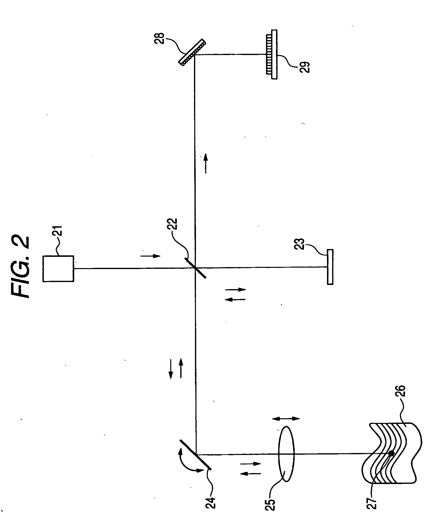
[0185]An image forming method using an optical coherence tomography which relates to this embodiment has the following steps.

[0186]1. A first image information obtaining step of obtaining a one-dimensional or two-dimensional image of an inspection object at a position, including a first focus, with respect to an optical axis direction, which is a direction in which light is directed onto the inspection object, by a spectral domain optical coherence tomography

[0187]2. A second image information obtaining step of obtaining a one-dimensional or two-dimensional image of the inspection object at a position, including a second focus different from the first focus, with respect to the optical axis direction by a spectral domain optical coherence tomography

[0188]3. A step of correcting positional relation, with respect to the optical axis direction, between both of image information obtained respectively by the first and second image information o...

third embodiment

SD-OCT with DF

[0191]In addition, an image forming method using an optical coherence tomography which relates to this embodiment is characterized by obtaining by a spectral domain optical coherence tomography a one-dimensional or two-dimensional image of an inspection object in an optical axis direction, in which light is directed onto the inspection object, respectively while changing a focal position with respect to an optical axis direction, and forming a tomography image or a three-dimensional image of the inspection object.

[0192]A focusing position can be defined by applying the above-described dynamic focusing mechanism.

[0193]In particular, data volume is reducible by leaving image information at a focusing position selectively, and eliminating the image information in other portions serially.

[0194]In the image forming method in this embodiment, unless a matter described in the above-described first embodiment is contradictory, it is applicable as it is.


PUM


Abstract

An image forming method uses an optical coherence tomography as to an optical axis direction of plural pieces of image information of an object. First image information of an object is obtained at a first focus with respect to an optical axis direction to then object. A focusing position is changed by dynamic focusing from the first focus to a second focus along the optical axis. The second image information of the object is obtained at the second focus. A third image information, tomography image information of the object and including a tomography image of the first focus or the second focus, is obtained by Fourier domain optical coherence tomography. A tomography image or a three-dimensional image of the object is formed in positional relation, in the optical axis direction, between the first image information and the second image information using the third image information.

Description

TECHNICAL FIELD[0001]The present invention relates to an image forming method and an optical coherence tomograph apparatus which use an optical coherence tomography.BACKGROUND ART[0002]Recently, imaging apparatuses using low coherence interferometry have been put in practical use. This is called an OCT (Optical Coherence Tomography or Optical Coherence Tomographic method).[0003]In an opthalmologic field, the OCT is used in order to obtain a tomography image of a fundus of the eye or its vicinity. In addition to the opthalmologic field, the OCT is used in an attempt to observe a tomography image of a skin, or to capture a wall surface tomography image of a digestive organ, a circulatory organ, and the like by incorporating the OCT in an endoscope or a catheter.[0004]As a type of the OCT, a method called TD-OCT (Time Domain OCT: a TIME DOMAIN method) is disclosed in U.S. Pat. No. 5,321,501. This method will be described briefly with reference to FIG. 32.[0005]Here, FIG. 32 is a schema...

Claims


Application Information

Patent Timeline
IPC IPC(8): G06K9/00G01B9/023
CPCA61B3/102G01N21/4795G01B9/02004G01B9/02085G01B9/02044G01B9/02027G01B9/02091G01B9/02011G01B9/02063G01B9/02048G01B2290/70G01B9/02077G01N2021/1787A61B5/004
Inventor SUGITA, MITSURONOZATO, KOJI
Owner FIFTH THIRD BANK
Why Eureka
Try Eureka