Throwaway Drill, Insert of Throwaway Drill and Cutting Method Using the Same

a technology of throwaway drill and insert, which is applied in the direction of twist drills, manufacturing tools, shaping cutters, etc., can solve the problems of inner cutting edge, outer insert of throwaway drill, and injuring the machined wall surface,

Inactive Publication Date: 2010-07-01
KYOCERA CORP
View PDF11 Cites 12 Cited by
  • Summary
  • Abstract
  • Description
  • Claims
  • Application Information

AI Technical Summary

Benefits of technology

[0018]An advantage of the invention is to provide a throwaway drill capable of achieving a cutting force balance between the inner edge insert and the outer edge insert, and an insert for a throwaway drill as well as a cutting method using the same.

Problems solved by technology

Therefore, when the drill is lifted from the hole, the outer edge insert might injure the machined wall surface.
However, it remains difficult for the throwaway drill 100 having the above construction to achieve a cutting force balance between the inner edge insert 105 and the outer edge insert 106 in a specific machining process such as offset machining.
However, when the offset machining is performed by using the above-mentioned throwaway drill 100, there remains the problem that the center height of an inner cutting edge 105a of the inner edge insert 105 is lowered and therefore the uncut remainder (the core) of the central part of the bottom worked becomes too large.
As a result, there arises the problem that the uncut remainder (the core) of the central part of the bottom worked becomes too large.
Heretofore, it has been unsuccessful in obtaining a throwaway drill that can prevent the core from becoming too large during offset machining, while achieving a balance between the cutting force exerted on the inner edge insert and the cutting force exerted on the outer edge insert.
However, in the insert for a throwaway drill of Patent Document No. 3, even if exhibited sufficient cutting edge strength as the inner cutting edge, when used as the outer cutting edge, the rake angle of the corner R cutting edge on the outer cutting edge is small and hence the cutting resistance of the outer cutting edge becomes large, causing the drill main body to be deflected.
Hence, there remains the problem that the desired working diameter cannot be obtained or the hole is bent.

Method used


Image

  • Throwaway Drill, Insert of  Throwaway Drill and Cutting Method Using the Same
  • Throwaway Drill, Insert of  Throwaway Drill and Cutting Method Using the Same
  • Throwaway Drill, Insert of  Throwaway Drill and Cutting Method Using the Same

Examples


first preferred embodiment

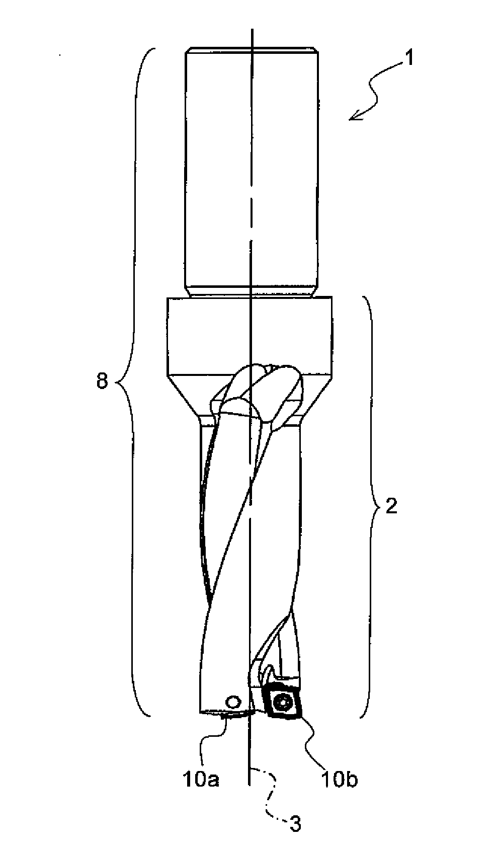
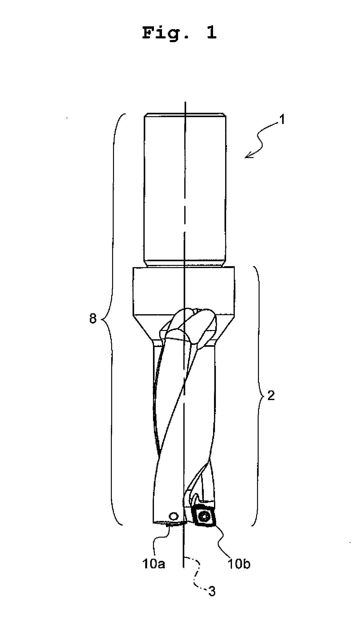
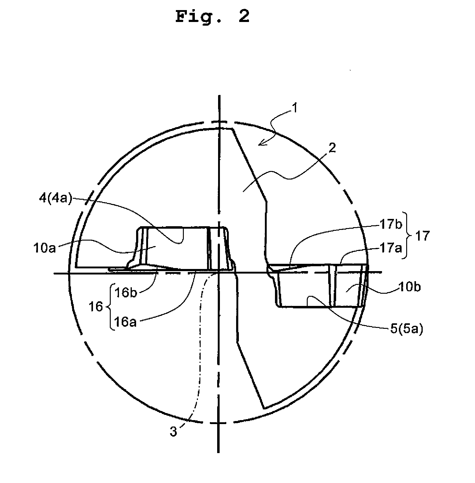
[0053]FIG. 1 is a front view showing a throwaway drill according to a first preferred embodiment of the invention. FIG. 2 is a diagram showing the arrangement of an inner edge insert and an outer edge insert when the throwaway drill in the first preferred embodiment is viewed from the tip end side thereof. FIG. 3(a) is a partially enlarged view showing the vicinity of the inner edge insert of the throwaway drill shown in FIG. 2, and FIG. 3(b) is a partially enlarged view showing the vicinity of the outer edge insert of the throwaway drill shown in FIG. 2. FIGS. 4(a) and 4(b) are a perspective view and a plan view of the insert for the throwaway drill of the first preferred embodiment, respectively.

[0054]As shown in FIGS. 1 to 3, a throwaway drill 1 of the present preferred embodiment includes a throwaway drill holder 8 provided with an inner edge insert pocket 4 which has a seat 4a and is formed on the side of a central axis 3 at the tip end of a bar-shaped drill main body 2, and wi...

second preferred embodiment

[0073]A throwaway drill and an insert for a throwaway drill according to a second preferred embodiment will be described in detail with reference to the accompanying drawings. FIG. 5 is an enlarged plan view of an insert for a throwaway drill according to the second preferred embodiment. FIG. 6(a) is a cross-sectional view taken along the line A-A in FIG. 5. FIG. 6(b) is a cross-sectional view taken along the line B-B in FIG. 5. FIG. 6(c) is a cross-sectional view taken along the line C-C in FIG. 5. FIG. 7 is a diagram showing the arrangement of an inner edge insert and an outer edge insert when the throwaway drill in the second preferred embodiment is viewed from the tip end side thereof. FIG. 8 is a partially enlarged side view showing the vicinity of the outer edge insert pocket in the second preferred embodiment. FIG. 9 is a partially enlarged schematic explanatory drawing showing the axial rake of the seat of the outer edge insert pocket in the second preferred embodiment. In F...


PUM

PropertyMeasurementUnit
inclination angleaaaaaaaaaa
rake angleaaaaaaaaaa

Abstract

A throwaway drill, an insert provided on the throwaway drill, and a cutting method using the same. The throwaway drill has a throwaway drill holder including an inner edge insert pocket having a seat, formed on a central axis side of a tip end of a drill main body, and an outer edge insert pocket having a seat, formed on the outer peripheral side of the tip end; an inner edge insert fixed to the seat of the inner edge insert pocket; and an outer edge insert fixed to the seat of the outer edge insert pocket. When viewed from the tip end side of the drill main body, the inner cutting edge of the inner edge insert includes: a first inner cutting edge provided on the central axis side of the drill main body, being parallel to at least part of the outer cutting edge of the outer edge insert; and a second inner cutting edge provided on the outer peripheral side of the drill main body, being inclined to the seat of the inner edge insert pocket in a direction toward the outer peripheral side, with respect to the first inner cutting edge.

Description

TECHNICAL FIELD[0001]The present invention relates to a throwaway drill and a drill insert for a throwaway drill, as well as a cutting method using the same. More particularly, the present invention relates to a throwaway drill provided with an insert for an inner edge and an insert for an outer edge, and an insert for a throwaway drill usable in either a cutting edge for an inner edge or a cutting edge for an outer edge, as well as a cutting method using the same.BACKGROUND ART[0002]As examples of drills used in drilling, there are solid-type drills, the entirety of which is integrally formed, and so-called throwaway drills in which a cutting edge for cutting is formed on an insert separated from a drill main body (a holder), and the cutting edge for cutting can be detachably mounted by a screw or the like on the tip end of the holder.[0003]In a generally known throwaway drill, the insert engaged with the tip end of the drill main body is constructed from two types of inserts, name...

Claims


Application Information

Patent Timeline
Patent Type & Authority Applications(United States)
IPC IPC(8): B23B51/00B23B27/16B23B27/22B23B35/00
CPCB23B51/02B23B51/048B23B2251/04B23B2251/14Y10T408/868Y10T408/905Y10T408/04Y10T408/892Y10T407/23Y10T408/9098Y10T407/235B23B51/00
Inventor OKUMURA, TAKASHI
Owner KYOCERA CORP
Why Eureka
Try Eureka