
Clamping method and device for cutting junction surface of semi-open thin-wall container

A thin-walled container, cutting processing technology, applied in the direction of positioning devices, metal processing equipment, metal processing machinery parts, etc., can solve the problems that cannot meet the requirements of dimensional accuracy, and achieve the effect of compact structure, high dimensional accuracy and light weight

Inactive Publication Date: 2015-07-15
JIANGSU UNIV OF SCI & TECH
View PDF13 Cites 0 Cited by
  • Summary
  • Abstract
  • Description
  • Claims
  • Application Information

AI Technical Summary

Problems solved by technology

However, the existing clamping methods and clamping devices cannot meet the requirements of dimensional accuracy when lathes process the joint surfaces of such polygonal semi-open thin-walled containers.

Method used


Image

  • Clamping method and device for cutting junction surface of semi-open thin-wall container

Examples


Embodiment 1

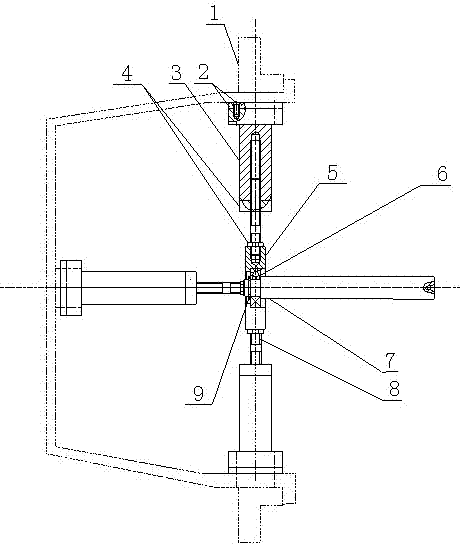
[0020] Embodiment 1: The thin-walled container workpiece is a triangular semi-open thin-walled container workpiece.

[0021] The outer jaw assembly 1 in this embodiment is a three-jaw chuck, and the radial compression head assembly 2 is divided into three groups, and each group of gaskets at the top of the compression head assembly 2 and each jaw of the outer jaw assembly 1 The positions are evenly distributed on the circumference in one-to-one correspondence.

[0022] The clamping method in this embodiment includes the following steps: when starting to process, the workpiece is first placed on the three-jaw chuck of the machine tool, the outer surface of the workpiece is in contact with the three-jaw chuck of the machine tool, and the machine tool tailstock is manipulated to drive the machine tool assembled on the machine tool tailstock. The movable top follows the tailstock shaft close to the center hole at one end of the central shaft 7, and adjusts the axial compression he...

Embodiment 2

[0023] Embodiment 2: The thin-walled container workpiece is a quadrilateral semi-open thin-walled container workpiece with unequal sides.

[0024] This embodiment is the turning of the joint surface of the oil pan part of the aluminum alloy material of the semi-opening thin-walled quadrilateral with unequal sides. Among them, the outer jaw assembly 1 is a four-jaw chuck, and the radial compression head assembly 2 is divided into four groups, and the gasket at the top of each group of compression head assembly 2 and each jaw position of the outer jaw assembly 1 are one by one. corresponds to a uniform distribution on the circumference.

[0025] The clamping method in this embodiment includes the following steps: when starting to process, the workpiece is first placed on the four-jaw chuck of the machine tool, the outer surface of the workpiece is in contact with the four-jaw chuck of the machine tool, and the tailstock of the machine tool is manipulated to drive the The movabl...


PUM


Abstract

The invention discloses a clamping method and a clamping device for cutting a junction surface of a semi-open thin-wall container. The method comprises the following steps of: jointly compacting a work piece by an internal support force generated by a set of axial compacting head components and a plurality of sets of radial compact head components and pressure of an external clamping claw component to the outer side of the work piece and the like. The device comprises an external clamping component used for fixing an outer wall of the work piece and a compacting head device used for compacting an inner all of the work piece, wherein the compacting head device comprises a set of axial compacting head components and a plurality of sets of radial compacting head components perpendicular to the compacting head components. The cutting force and the clamping force can be tended to be balanced, and the device has the advantages of being compact in structure, small in volume, and light in weight; and the shape-accordant clamps and screw studs of the clamps with different combination are changed, so that not only can the junction surfaces of parts with different sizes and different polygons be machined, but also the high efficiency, the high size precision, the good planeness and the low cost for machining the work piece can greatly meet the requirement of production.

Description

technical field [0001] The invention relates to a process method and a device for cutting a joint surface of a polygonal semi-open thin-walled container, in particular to a clamping method and a device for cutting the joint surface of a semi-open thin-walled container. Background technique [0002] At present, polygonal semi-open thin-walled containers are widely used in various fields due to their lighter weight and less material than other shapes and cross-sections. Because the polygonal semi-open thin-walled container is easy to deform, especially the joint surface of the polygonal semi-open thin-walled container needs to be assembled with other structural parts and requires sealing. Planing is complete. Since the joint surface of the polygonal semi-open thin-walled container is on the entire top of the planer fixture, it is inconvenient for the planer fixture to be pressed from top to bottom, and can only be clamped from the side; and because the polygonal semi-...

Claims


Application Information

Patent Timeline
Patent Type & Authority Patents(China)
IPC IPC(8): B23Q3/00
Inventor 任家隆王波王明建管小燕严帅吴爱胜
Owner JIANGSU UNIV OF SCI & TECH
Learn More