Partitioning features of a single IC layer onto multiple photolithographic masks

a technology of ic layer and mask, which is applied in the direction of photomechanical treatment originals, photomechanical instruments, photomechanical devices, etc., can solve the problems of difficult patterning interconnect lines, difficult manufacturing perspective to continue shrinking device features from one technology node to the next, and lack of contrast between exposed and un-exposed photoresist regions

Active Publication Date: 2010-07-01
TEXAS INSTR INC
View PDF2 Cites 26 Cited by
  • Summary
  • Abstract
  • Description
  • Claims
  • Application Information

AI Technical Summary

Benefits of technology

[0005]The following presents a summary to provide a basic understanding of one or more aspects of the disclosure herein. This summary is not an extensive overview. It is intended neither to identify key or critic...

Problems solved by technology

Although shrinking is often advantageous from a performance perspective, it is often difficult from a manufacturing perspective to continue to shrink device features from one technology node to the next.
In particular, it is becoming particularly difficult to pattern interconnect lines, which tend to be very closely spaced.
Thus, d...

Method used


Image

  • Partitioning features of a single IC layer onto multiple photolithographic masks
  • Partitioning features of a single IC layer onto multiple photolithographic masks
  • Partitioning features of a single IC layer onto multiple photolithographic masks

Examples


Embodiment Construction

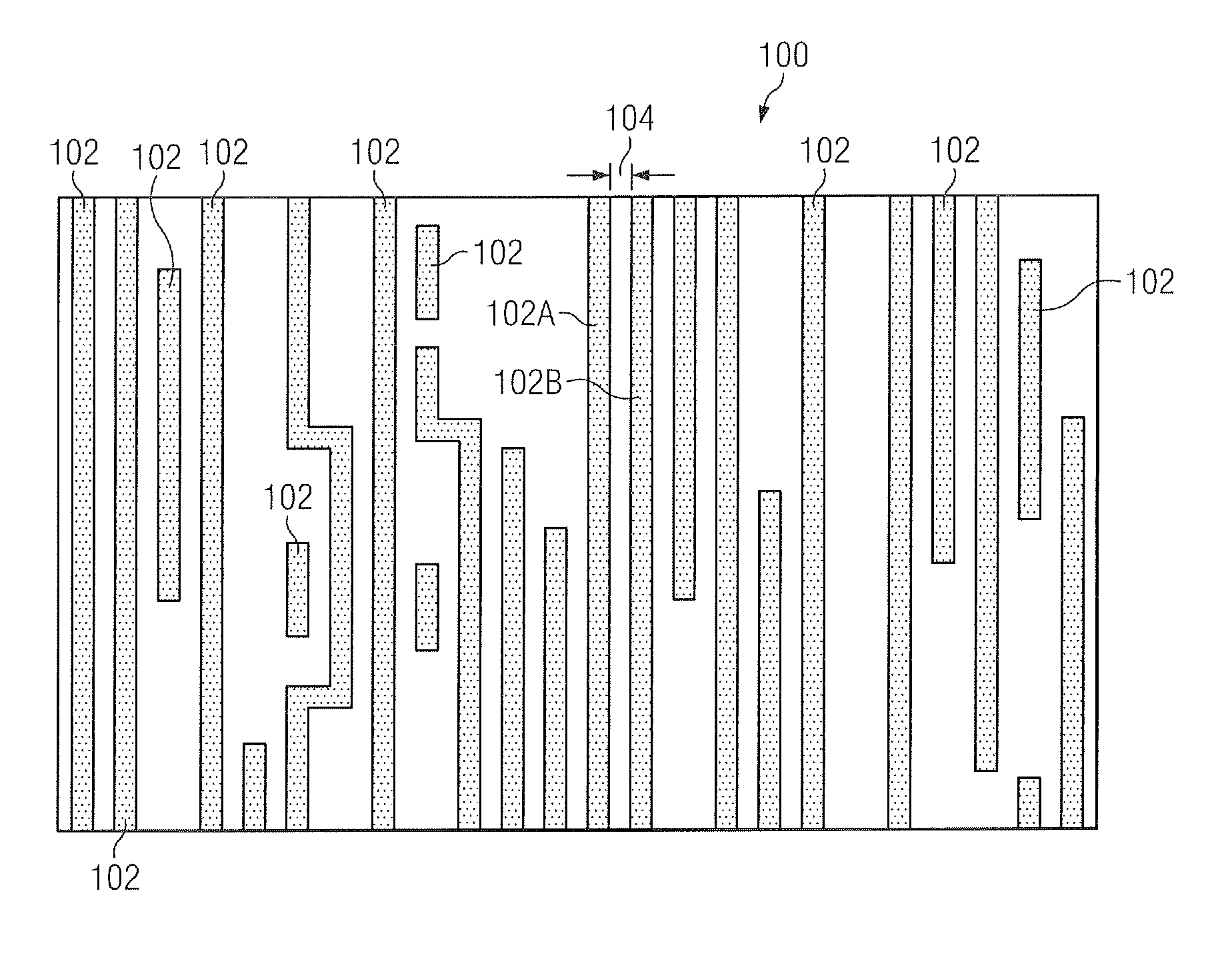
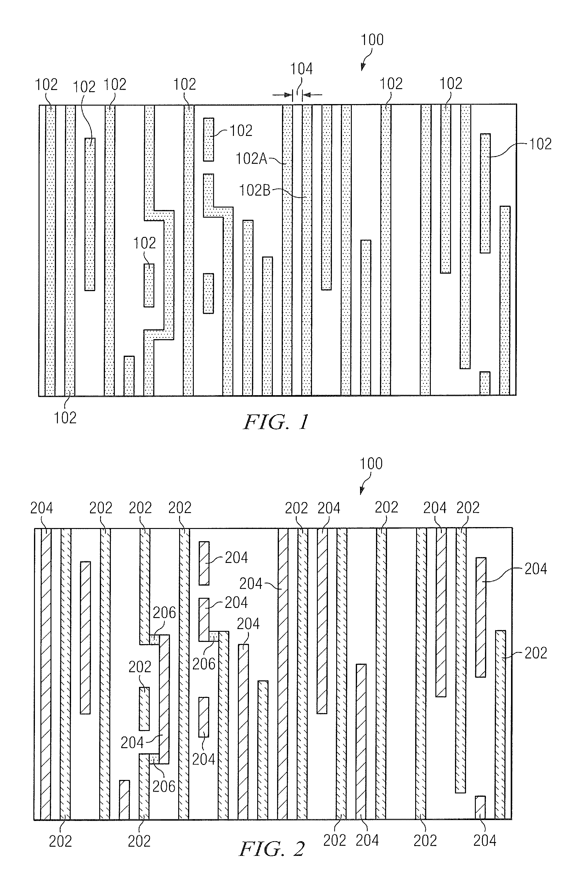
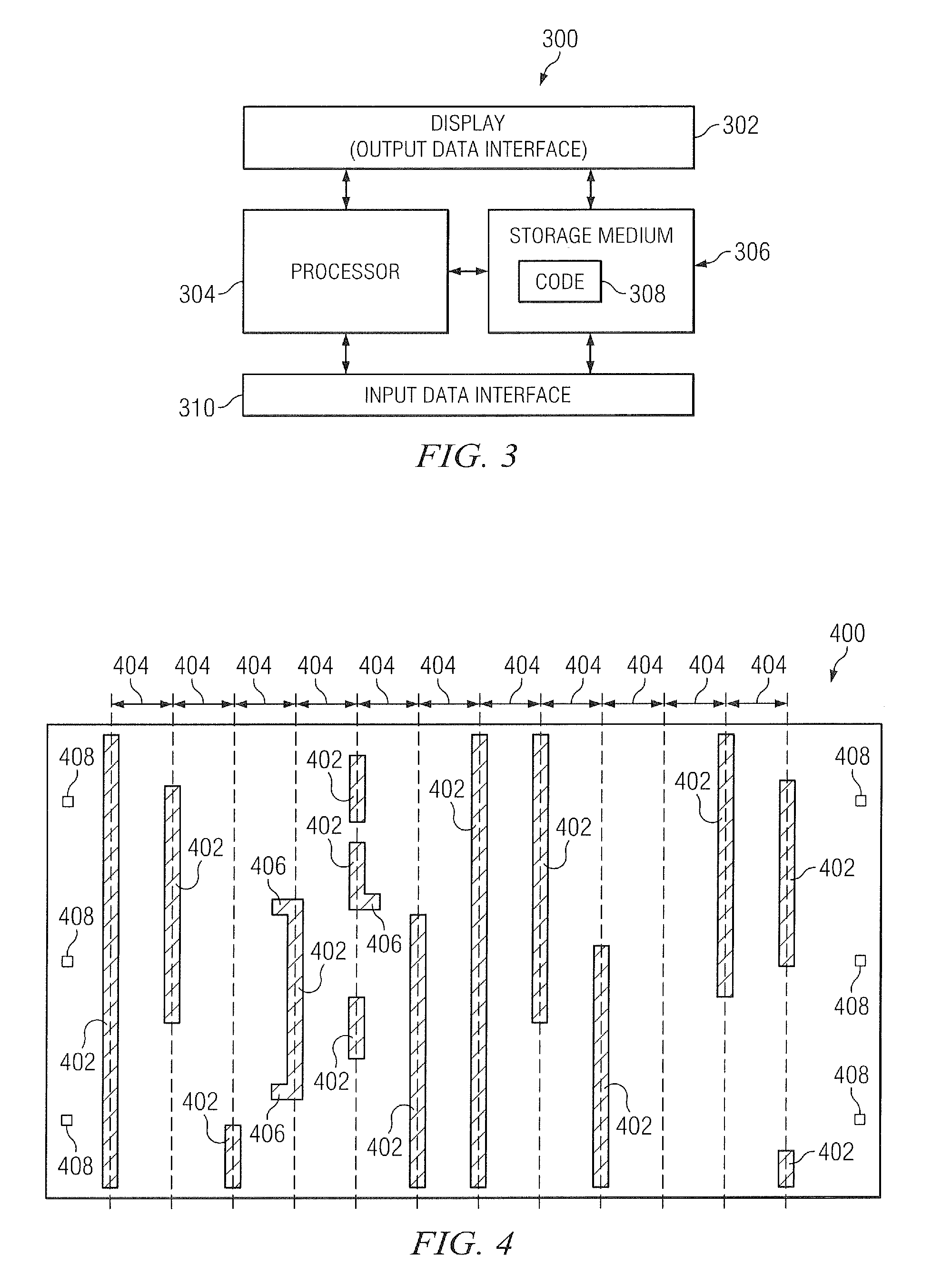
[0021]The description herein is made with reference to the drawings, wherein like reference numerals are generally utilized to refer to like elements throughout, and wherein the various structures are not necessarily drawn to scale. In the following description, for purposes of explanation, numerous specific details are set forth in order to facilitate understanding. It may be evident, however, to one skilled in the art, that one or more aspects described herein may be practiced with a lesser degree of these specific details. For example, as provided herein longitudinal lines are often described comprising a fixed pitch of 60 nm, however, one skilled in the art will appreciate that that the longitudinal lines may comprise any fixed pitch (e.g., 40 nm, 65 nm, etc.) or alternative longitudinal lines may comprise substantially fixed pitches (e.g., 60 nm + / −10 nm) resulting in an average fixed pitch (e.g., a mask having longitudinal lines with a fixed pitch of 118 nm and a mask having l...


PUM


Abstract

One embodiment relates to a computer method of providing an electronic mask set for an integrated circuit (IC) layer. In the method, a first electronic mask is generated for the IC layer. The first electronic mask includes a first series of longitudinal segments from the IC layer, where the first series has fewer than all of the longitudinal segments in the IC layer. A second electronic mask is also generated for the IC layer. The second electronic mask includes a second series of longitudinal segments from the IC layer, where the second series has fewer than all of the longitudinal segments in the IC layer and differs from the first series. The first and second masks are generated so a coupling segment extends traverse to the first direction and couples one longitudinal segment on the IC layer to another longitudinal segment on the IC layer.

Description

FIELD[0001]The disclosure herein relates generally to integrated circuits, and more particularly for systems and methods for using multiple lithographic masks to pattern a single layer on an integrated circuit.BACKGROUND[0002]Integrated circuits are generally mass produced by semiconductor design companies. In designing the integrated circuit, engineers at a design company use computer-aided tools to develop an electronic mask set, which represents different layers of the integrated circuit. This electronic mask set is then used to generate a set of physical masks, which are in turn used to fashion features on different layers of a physical integrated circuit during manufacturing.[0003]As design companies strive to deliver more powerful integrated circuits at lower cost points, the design companies continuously try to “pack” more transistors into a given area on each integrated circuit. This is often achieved by shrinking feature sizes of the devices, which generally results in inte...

Claims


Application Information

Patent Timeline
IPC IPC(8): H01L21/3205G06F17/50G03F1/00G03F7/20
CPCG03F1/70G03F1/42
Inventor ATON, THOMAS J.
Owner TEXAS INSTR INC
Why Eureka
Try Eureka