Cooler for bulk material having a sealing device between adjoining conveying planks

a technology of sealing device and bulk material, which is applied in the direction of lighting and heating apparatus, discharged material handling, combustion process, etc., can solve the problems of material falling into the grate pit, affecting the operation of the cooling apparatus, so as to eliminate the risk of blockage of the outer sealing element by recycled stray material and ensure the effect of sealing

Inactive Publication Date: 2010-07-08
CLAUDIUS PETERS PROJECTS
View PDF1 Cites 8 Cited by
  • Summary
  • Abstract
  • Description
  • Claims
  • Application Information

AI Technical Summary

Benefits of technology

[0024]Preferably, the inner sealing element is designed such that its flow resistance is less than that of the outer sealing element. The effect is that the gas flowing in the conveying duct does not flow backward through the outer sealing element back into the bulk material bed. The risk of blockages of the outer sealing element by recycled stray material is thereby eliminated. A ratio of, for example, 1:2 to 1:50 has proved successful.
[0025]It can be expedient to configure the

Problems solved by technology

In this conveying principle, which is also referred to as a “walking floor”, one difficulty consists in the fact that at the boundaries between adjoining planks bulk material falls through into a grate pit.
In coolers, unlike in comparable grates of furnaces, this poses a considerable problem.
The accumulation of bulk material which has fallen through the grate is undesirable and leads to wear and ultimately damage to components of the cooling apparatus.
In this context, the construction featuring the longitudinally moved planks is particularly problematical, since both a same movement between the adjoining planks and a contrary movement can take

Method used


Image

  • Cooler for bulk material having a sealing device between adjoining conveying planks
  • Cooler for bulk material having a sealing device between adjoining conveying planks
  • Cooler for bulk material having a sealing device between adjoining conveying planks

Examples


Embodiment Construction

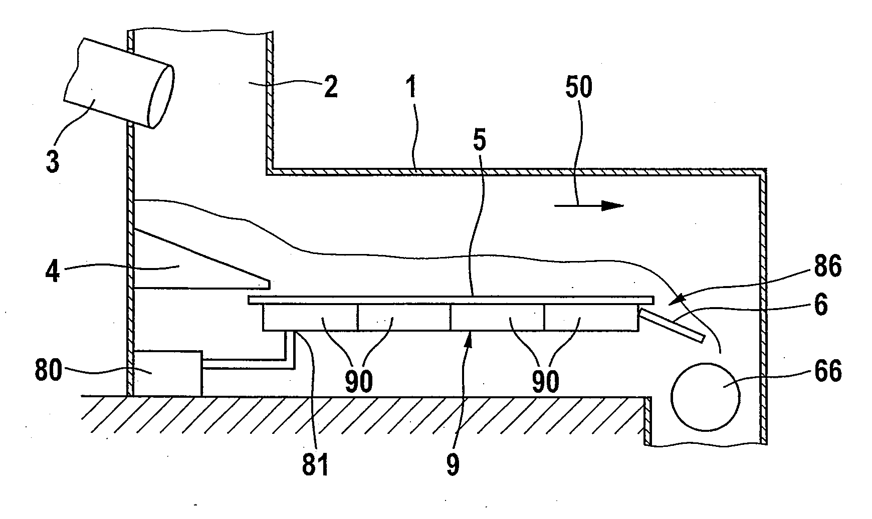
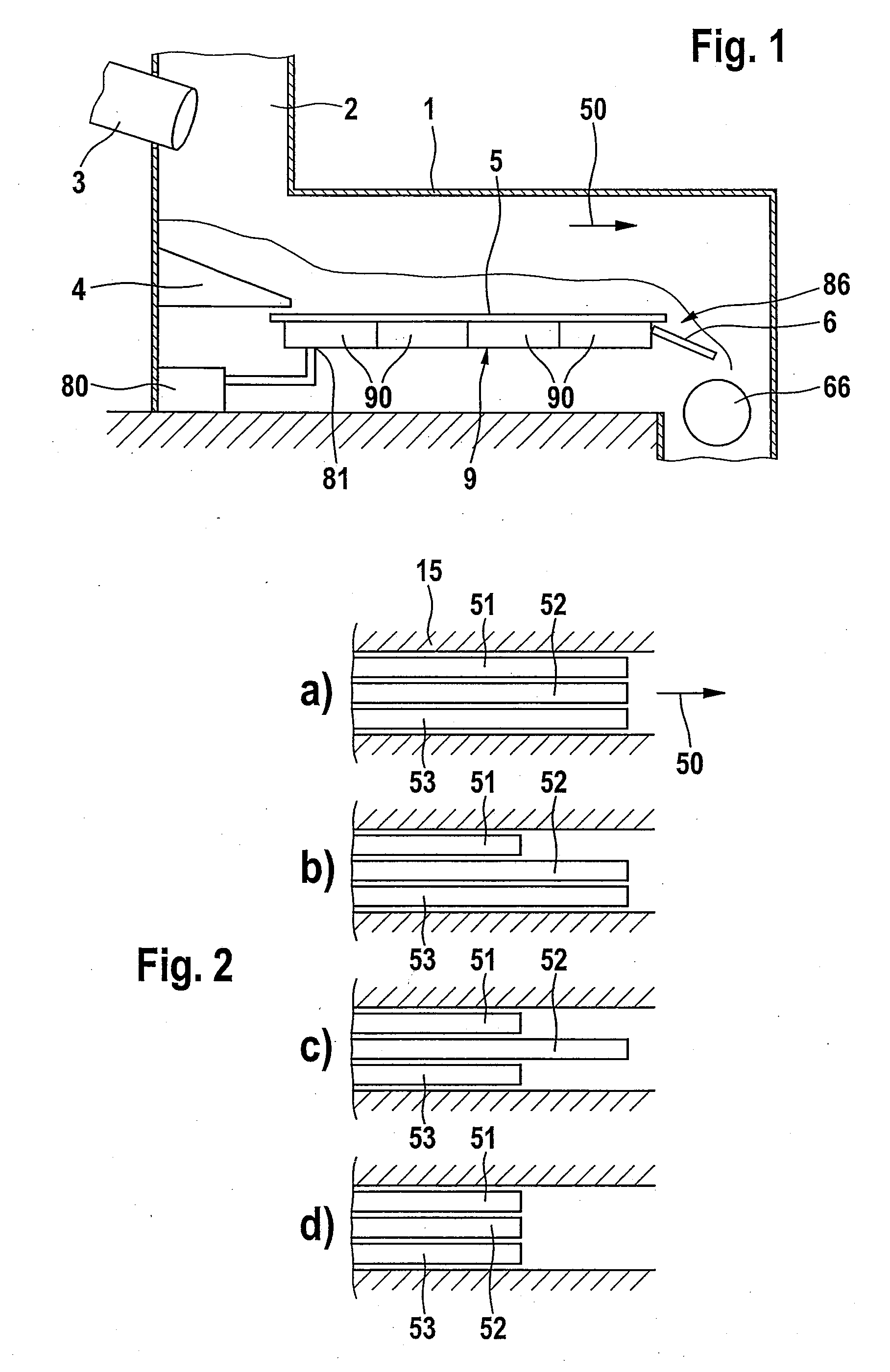
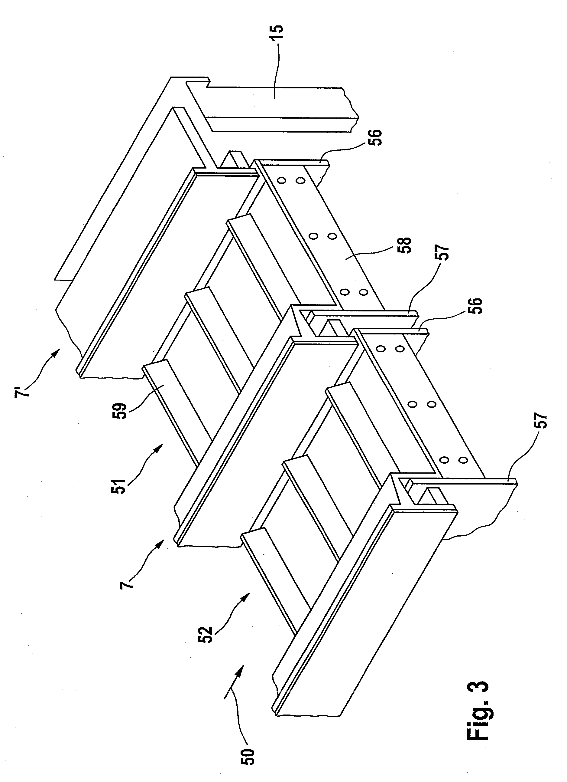
[0034]In FIG. 1, a schematized view of a cooling apparatus and its integration in a cooling plant is represented. Located at the beginning in a cooler housing 1 is a feed shaft 2, into which a discharge pipe 3 of an upstream rotary furnace (not represented) emerges. Material emanating from the rotary furnace falls into the feed shaft 2 onto a cooling grate, more precisely onto its feed end 4. It has a slightly downward-sloping, ramp-shaped design, so that the deposited material slides in the direction of a horizontally disposed main portion of the grate. If the grate is referred to below without further detail, then this main portion 5 of the cooling grate is meant. It has a plurality of longitudinally movable planks 51-53, which exert a conveying effect upon the material such that it is led away from the feed end 4 and along the grate 5. At the opposing ends, the grate has a delivery end 6, that in the illustrative embodiment is configured as an inclined skidpan. It serves to disch...


PUM


Abstract

An apparatus for cooling bulk material with a grate flowed through by cooling gas. The apparatus comprises a plurality of planks configured to move forward and back in the direction of conveyance and, between the planks, a sealing device having spatially separate outer and inner sealing elements. The sealing device has between the sealing elements a conveying duct, which runs along the length of the planks and on which a gas supply is configured to produce a gas stream along the length of the conveying duct. Bulk material which has infiltrated through the outer sealing element can be transported away before it can reach and migrate through the inner sealing element. The accompanying sealing effect can considerably reduce the undesirable material through-fall, while enabling the use of low-wearing seals, which provide excellent wear resistance.

Description

REFERENCE TO RELATED APPLICATIONS[0001]This application is a national stage application under 35 USC 371 of International Application No. PCT / EP2007 / 007102, filed Aug. 10, 2007, which claims priority of European Patent Application No. 06 016 751.7, filed Aug. 10, 2006, the contents of which are incorporated herein by reference in their entirety.FIELD OF THE INVENTION[0002]The invention relates to an apparatus for cooling bulk material with a gas, which apparatus has a grate which conveys a layer of the bulk material from a feed end in a direction of conveyance to a delivery end and is flowed through by cooling gas, wherein the grate comprises a plurality of planks moved alternately forward and back in the direction of conveyance and, between adjoining planks, a sealing device is provided, comprising two mutually separate sealing elements.BACKGROUND OF THE INVENTION[0003]Cooling apparatuses of this type serve to cool bulk material through the use of gas, in that the bulk material is ...

Claims


Application Information

Patent Timeline
IPC IPC(8): F26B25/00B65G25/04
CPCB65G25/065F26B17/26F28F2230/00F28C3/16F27D15/0213
Inventor DIKTY, MARIOHILGRAF, PETERSTAAK, THOMASSPRINZ, UWEMEYER, HARTMUTBOCK, UWEKNABBE, JOERNKOEBERER, GUENTHER
Owner CLAUDIUS PETERS PROJECTS
Why Eureka
Try Eureka