
Dampened recoil rest for supporting a rifle

Active Publication Date: 2010-07-08
WERNER THEODORE J
View PDF7 Cites 15 Cited by
  • Summary
  • Abstract
  • Description
  • Claims
  • Application Information

AI Technical Summary

Benefits of technology

[0013]Thus, an object of the embodiments of the present invention is to provide a dampened recoil rest for supporting a rifle for enabling a shooter to operate the rifle with adjustable attenuation of recoil felt by the shooter, eliminating damage to the rifle by progressively absorbing or attenuating recoil, with the sight remaining on the target thereby eliminating a need to reacquire the target, without having to add additional weight to absorb the recoil, and with comfortable transfer of the recoil from the rifle to the shooter's shoulder, which avoids the disadvantages of the prior art.

Problems solved by technology

Currently, there exists in the art the following problems:Rifles produce recoil that is uncomfortable to many shooters.Current designs of rests that eliminate recoil could cause damage to the rifle, especially its stock, because the amount of resistance often is excessive, thus causing too much stress to be absorbed by the stock.At times it is desirable for the shooter to select an amount of recoil to deal with.
This selection is quite difficult to achieve using shooting rests according to current designs.Current designs of shooting rests that eliminate recoil do not return to battery, i.e., they move all over a bench top.
Thus, the target moves out of the field of view, thereby compromising target reacquisition.Many popular shooting rests require addition of a heavy weight to attenuate recoil.
This weight addition is inconvenient and cumbersome.Many popular shooting rests do not allow the shooter to shoot the rifle comfortably from the shoulder.

Method used


Image

  • Dampened recoil rest for supporting a rifle
  • Dampened recoil rest for supporting a rifle
  • Dampened recoil rest for supporting a rifle

Examples


Embodiment Construction

A. General

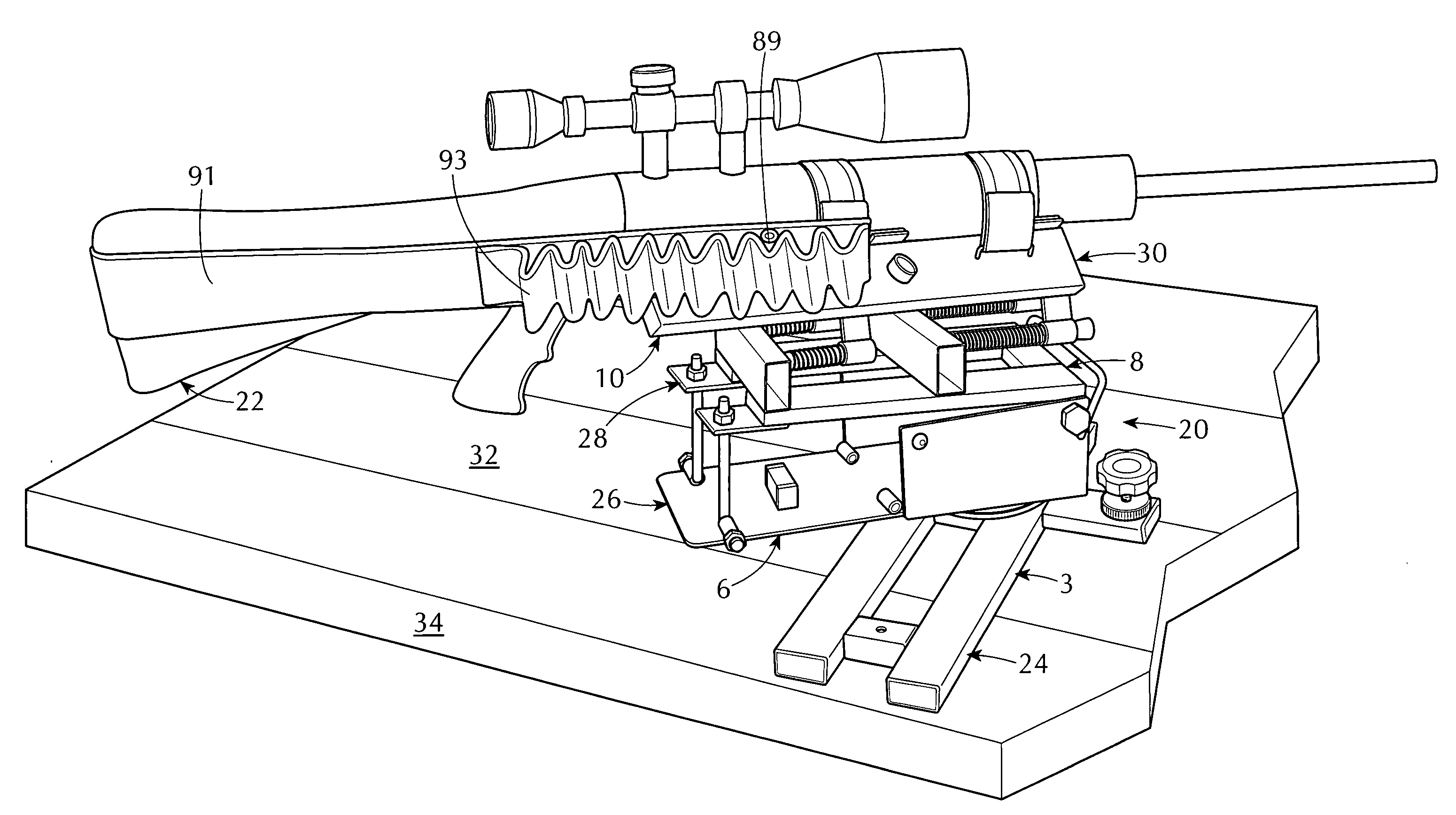
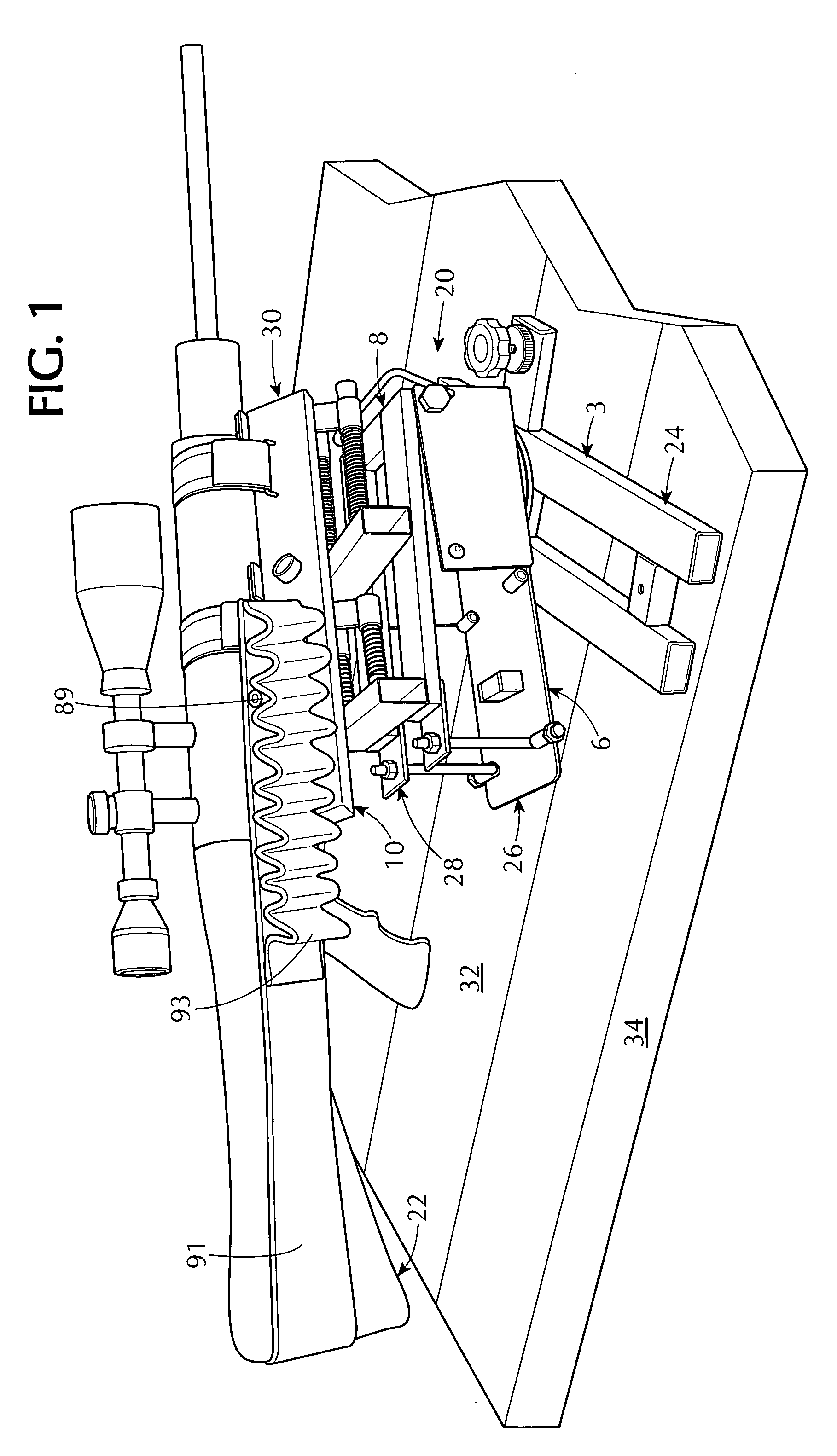
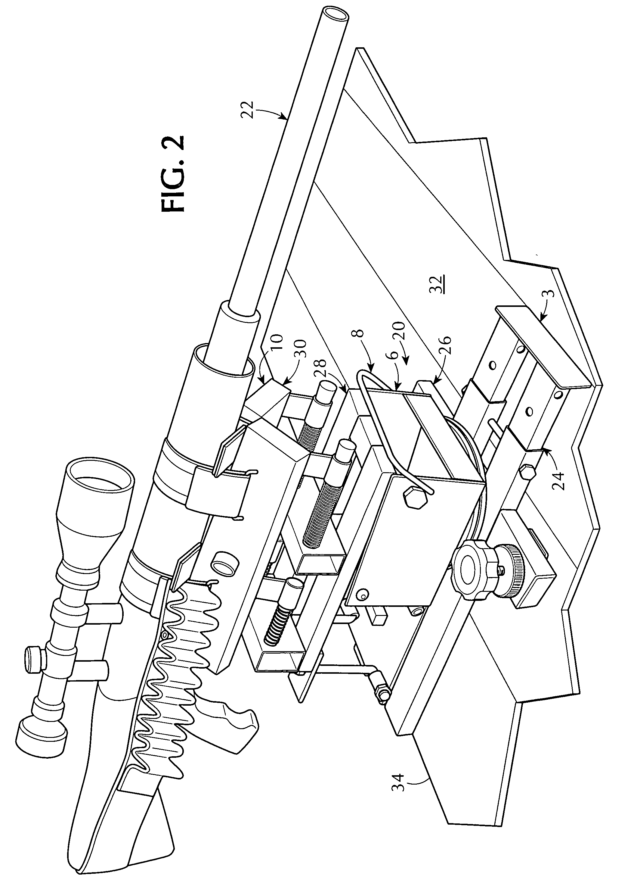
[0078]Referring now to the figures, in which like numerals indicate like parts, and particularly to FIGS. 1 and 2, which are, respectively, a diagrammatic rear perspective view of the dampened recoil rest of the embodiments of the present invention supporting a rifle and enabling a shooter to operate the rifle with adjustable attenuation of recoil felt by the shooter, eliminating damage to the rifle by progressively absorbing or attenuating recoil, with the sight remaining on the target thereby eliminating a need to reacquire the target, without having to add additional weight to absorb the recoil, and with comfortable transfer of the recoil from the rifle to the shooter's shoulder, and a diagrammatic front perspective view of the dampened recoil rest of the embodiments of the present invention supporting a rifle and enabling a shooter to operate the rifle with adjustable attenuation of recoil felt by the shooter, eliminating damage to the rifle by progressively absorbing ...


PUM


Abstract

A dampened recoil rest for supporting a rifle for enabling a shooter to operate the rifle with adjustable attenuation of recoil felt by the shooter, eliminating damage to the rifle by progressively absorbing or attenuating recoil, with the sight remaining on the target thereby eliminating a need to reacquire the target, without having to add additional weight to absorb the recoil, and with comfortable transfer of the recoil from the rifle to the shooter's shoulder. The rest includes a stationary base assembly, a rotating base assembly, a recoil attenuating assembly, and a rifle support assembly. The stationary base assembly is for attaching to a bench top. The rotating base assembly is rotatably attached to the stationary base assembly. The recoil attenuating assembly is operatively connected to the rotating base assembly and is for enabling the shooter to operate the rifle with adjustable attenuation of the recoil felt by the shooter, with the sight remaining on the target thereby eliminating a need to reacquire the target, without having to add additional weight to absorb the recoil, and with the comfortable transfer of the recoil from the rifle to the shooter's shoulder. The rifle support assembly is operatively connected to the recoil attenuating assembly and is for supporting the rifle.

Description

1. CROSS REFERENCE TO RELATED APPLICATIONS[0001]The instant nonprovisional patent application claims priority from provisional patent application No. 61 / 204,500, filed on Jan. 7, 2009, by Theodore J. Werner, for a KIT FOR DAMPENED RECOIL OF FIREARM, and incorporated herein by reference thereto.2. BACKGROUND OF THE INVENTION[0002]A. Field of the Invention[0003]The embodiments of the present invention relate to a dampened recoil rest for supporting a rifle, and more particularly, the embodiments of the present invention relate to a dampened recoil rest for supporting a rifle for enabling a shooter to operate the rifle with adjustable attenuation of recoil felt by the shooter, eliminating damage to the rifle by progressively absorbing or attenuating recoil, with the sight remaining on the target thereby eliminating a need to reacquire the target, without having to add additional weight to absorb the recoil, and with comfortable transfer of the recoil from the rifle to the shooter's sho...

Claims


Application Information

Patent Timeline
IPC IPC(8): F41A35/00
CPCF41A23/16F41A25/10
Inventor WERNER, THEODORE J.
Owner WERNER THEODORE J
Learn More