Bending apparatus and bending machine

a technology of bending apparatus and bending machine, which is applied in the direction of electrical apparatus, dynamo-electric machines, manufacturing dynamo-electric machines, etc., can solve the problems of difficult control of material dimension, complex mechanism, and difficulty in combining a plurality of bending apparatuses to bend the material at a plurality of portions simultaneously, so as to ensure the material cannot be pulled, the effect of accurately performing the bending of a flat rectangular wire and excellent quality

Active Publication Date: 2010-07-08
AISIN AW CO LTD
View PDF14 Cites 23 Cited by
  • Summary
  • Abstract
  • Description
  • Claims
  • Application Information

AI Technical Summary

Benefits of technology

[0020]According to the invention according to a third aspect of the present invention, the material can surely be prevented from being pulled in.
[0021]According to the invention according to a fourth aspect of the present invention, bending of a flat rectangular wire can accurately be performed without damaging an insulating enamel layer during the bending. Therefore, motor coils of an excellent quality can be obtained.
[0022]According to the invention according to a fifth aspect of the present invention, the material can be bent simultaneously at a plurality of portions. Therefore, complicated bending shapes can be achieved accurately and in a short time, thereby reducing the manufacturing costs. Specifically, according to the bending apparatus according to the first to fourth aspects, the material is prevented from being pulled in during the bending. Therefore, even when a plurality of the bending apparatuses are combined as in the invention according to the fifth aspect and the material is bent simultaneou

Problems solved by technology

As a result, the required mechanism is complicated and may not be capable of performing an accurate bending.
Additionally, as described above, when the material 2 is displaced relative to the first jig 3 when the bending is performed, it is difficult to comb

Method used


Image

  • Bending apparatus and bending machine
  • Bending apparatus and bending machine
  • Bending apparatus and bending machine

Examples


first embodiment

[0041]In the following, referring to FIGS. 1 to 6, a first embodiment of the present invention will be described.

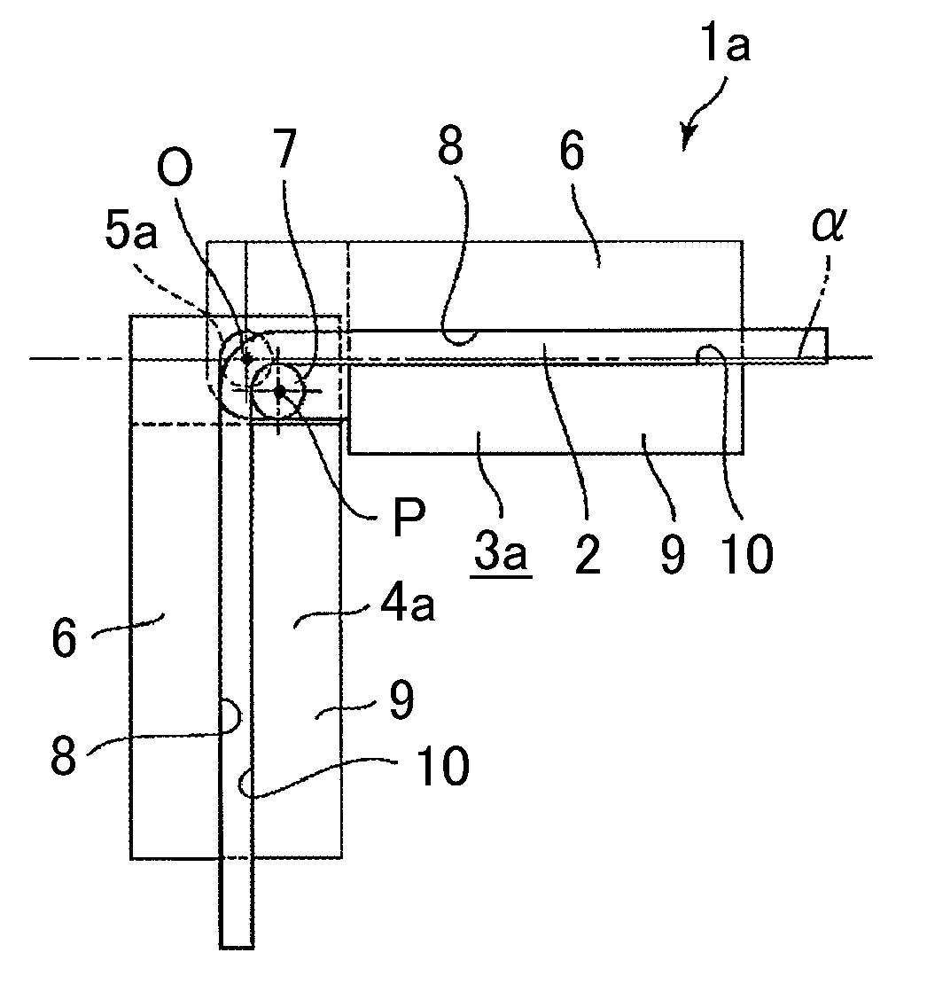
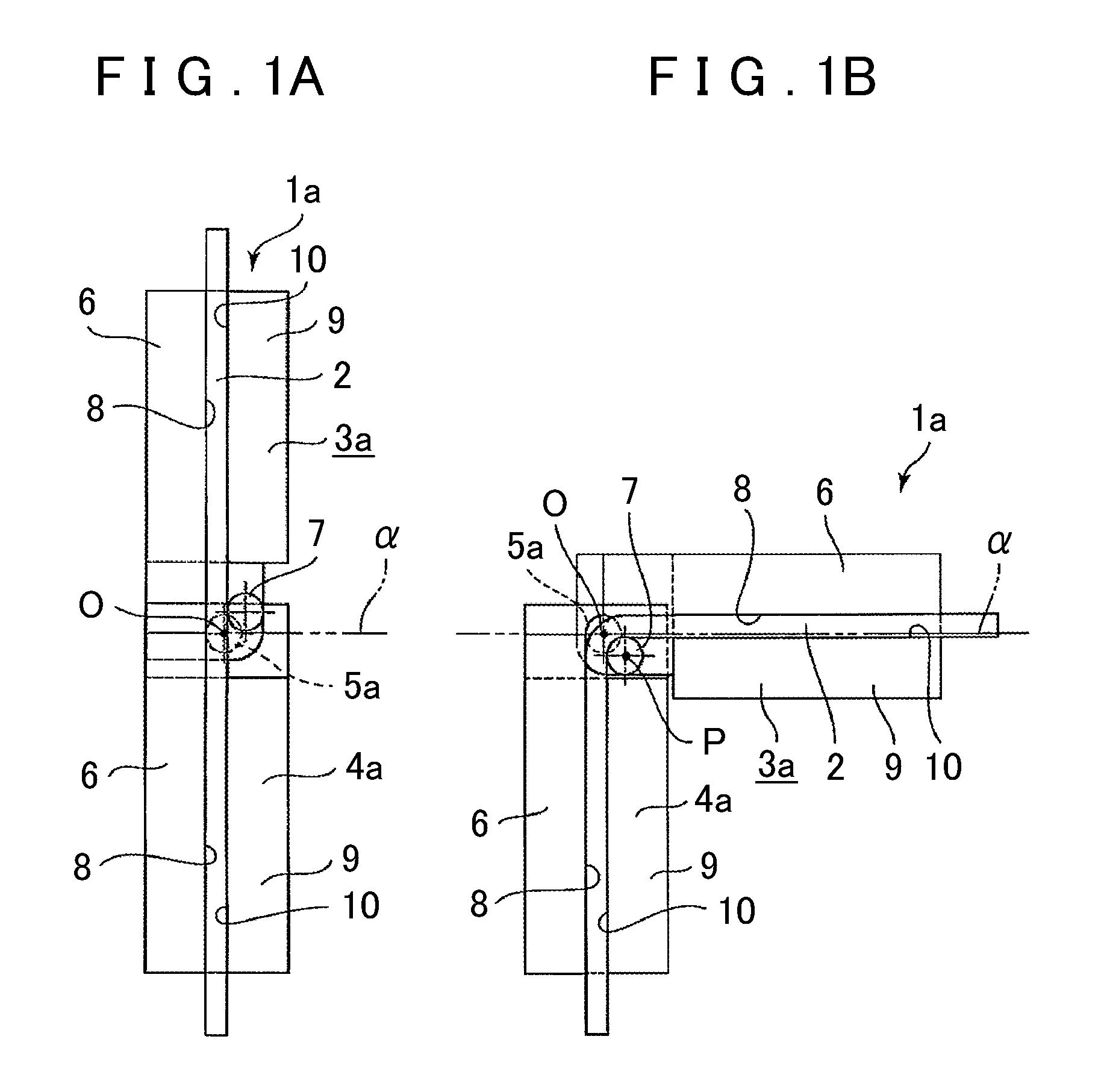
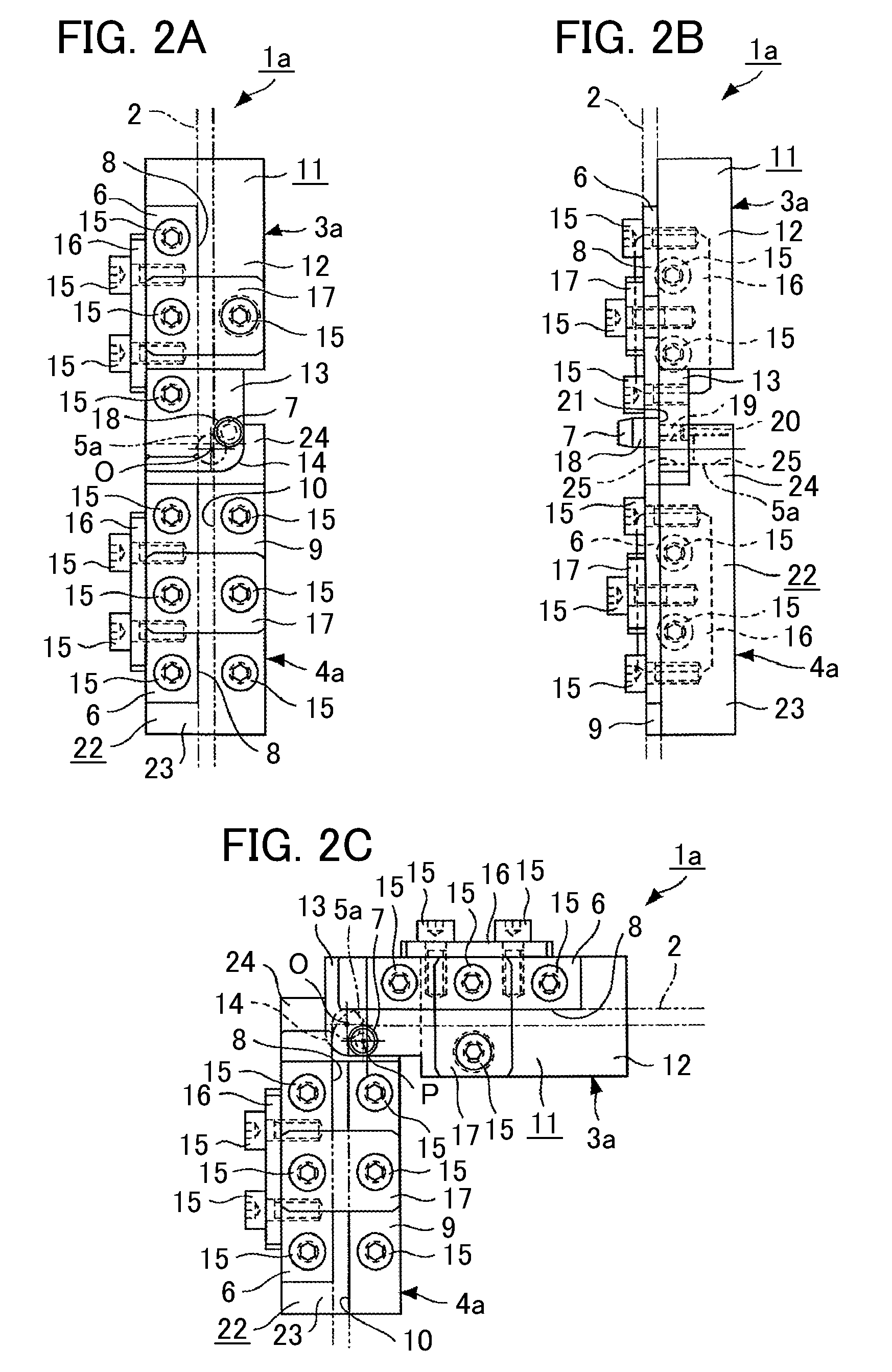
[0042]First, an overview of a bending apparatus 1a of the present embodiment is described referring to a schematic diagram of FIG. 1. The bending apparatus 1a is structured with first and second jigs 3a and 4a that are coupled by a rotary shaft 5a so as to be rotatable relatively to each other. The first jig 3a includes a suppressing section 6, a bending section 7, and a holding section 9. The suppressing section 6 is arranged on the side opposite to the rotating direction of a material 2, e.g., a flat rectangular wire having a rectangular cross section, in a state where the material 2 is arranged at the first jig 3a. In the state where the material 2 is so arranged, a suppressing surface 8 of the suppressing section 6 abuts on the material 2.

[0043]The bending section 7 is formed to have a cylindrical outer peripheral surface, and the center of which is arranged at a posi...

second embodiment

[0070]FIG. 7 shows a bending apparatus 1b according to a second embodiment of the present invention, in which the bending section 7 according to the first embodiment has a modified shape. In the following, description will be given mainly on the difference from the first embodiment.

[0071]As shown in FIG. 7, at a bending section 7a structuring a first jig 3b, a bending cylindrical surface 18a forming a quarter of a circle as seen from the perpendicular direction to the surface of FIG. 7 is formed on the tip surface of a rectangular portion 26 which is elongated along the axial direction of the material 2 and whose cross section perpendicular to the axial direction is rectangular. The bending cylindrical surface 18a is a partially cylindrical surface provided at a contiguous portion between the side surface of the bending section 7a on the material 2 side and the tip surface of the bending section 7a. A center axis (the axis passing through the center of curvature) of the bending cyli...

third embodiment

[0073]FIGS. 8 to 13 show a bending machine 27 according to a third embodiment of the present invention, structured by a combination of a plurality of bending apparatuses such as described above. Each of the bending apparatuses is structured similarly as in the first embodiment. First, an overview of the bending machine 27 according to the present embodiment is described referring to FIG. 8.

[0074]The bending machine 27 is structured by arranging a plurality of bending apparatuses 1a in series, by alternately coupling the first jigs 3a and the second jigs 4a at the rotary centers O, so that the material 2 can be bent at a plurality of portions. To this end, between a pair of end jigs 28a and 28b, three intermediate jigs 29a, 29b and 29c are arranged. Among them, the end jig 28a arranged on the bottom side in FIG. 8A is provided with the second jig 4a at one end (the top side in FIG. 8A). The end jig 28b arranged on the top side in FIG. 8A is provided with the first jig 3a at the other...


PUM

PropertyMeasurementUnit
Angleaaaaaaaaaa
Forceaaaaaaaaaa
Radiusaaaaaaaaaa

Abstract

A bending apparatus for performing accurate non-destructive bending of material includes first and second jigs that are rotatable about a rotary shaft and that bend the material attached to the jigs as they rotate relative to each other. The first jig includes a bending section that is arranged offset from a rotary center to a rotating side of the material and that has a partially cylindrical surface with a radius of curvature corresponding to the radius of curvature of an inner peripheral surface of the material. Each of the first and second jigs has a suppressing section for suppressing displacement of the material, and a bending center of the material is arranged such that the material is not displaced relative to the first and second jigs when the material is bent.

Description

INCORPORATION BY REFERENCE[0001]The disclosure of Japanese Patent Application No. 2009-002187 filed on Jan. 8, 2009 including the specification, drawings and abstract is incorporated herein by reference in its entirety.BACKGROUND OF THE INVENTION[0002]The present invention relates to a bending apparatus and a bending machine that bends a prescribed material, such as metal wires having a circular or rectangular cross section for forming motor coils (e.g. a flat rectangular wire), or rods, pipes, plates and the like. Particularly, the present invention relates to a bending apparatus and a bending machine that can perform bending of the material accurately by eliminating pull-in of the material that may occur when the material is bent.DESCRIPTION OF THE RELATED ART[0003]Generally, motor coils and the like are obtained by bending of a material, such as a metal, wire by winding the material around a bending jig. In related art, a method has been proposed in Japanese Patent Application Pu...

Claims


Application Information

Patent Timeline
IPC IPC(8): B21F1/00B21D7/04
CPCB21D7/02B21D7/024B21D7/04B21F1/00H02K15/0478
Inventor SAITO, MASAKIHASHIMOTO, SHINGOSHINDO, FUMIO
Owner AISIN AW CO LTD
Why Eureka
Try Eureka