Automatic transmission

a transmission and automatic technology, applied in the direction of gear lubrication/cooling, clutches, non-mechanical actuators, etc., can solve the problems of mechanical efficiency degradation of the transmission, and achieve the effect of improving transmission efficiency and reducing the drag of the brake uni

Inactive Publication Date: 2010-07-08
TOYOTA JIDOSHA KK
View PDF2 Cites 7 Cited by
  • Summary
  • Abstract
  • Description
  • Claims
  • Application Information

AI Technical Summary

Benefits of technology

[0009]The invention has been designed in consideration of the technical problems described above, and an object thereof is to provide an automatic transmission with which the effects of drag in a brake unit can be reduced, leading to an improvement in transmission efficiency.
[0011]In this constitution, surplus lubricating oil discharged from the clutch gathers in the brake. The surplus lubricating oil that gathers in the brake is guided to and trapped in the surplus lubricating oil trapping space defined by the inner peripheral surface of the transmission case and the separating / guiding wall, which is subject to axial or axial and rotational movement restriction by the holding mechanism. The surplus lubricating oil trapped in the trapping space then flows downward in the circumferential direction. Thus, contact between the surplus lubricating oil and the rotating piston, clutch drum and clutch is avoided, leading to a reduction in agitation loss.
[0015]Incidentally, it is necessary to prevent backlash (backflow) from lubricating oil that flies from first and second clutches due to high-speed rotation thereof.
[0017]According to the invention, an automatic transmission with which the effects of drag in a brake unit can be reduced, leading to an improvement in transmission efficiency, can be provided.

Problems solved by technology

As a result, the mechanical efficiency of the transmission deteriorates.

Method used


Image

  • Automatic transmission
  • Automatic transmission
  • Automatic transmission

Examples


first embodiment

[0085]According to this embodiment, the following actions and effects are obtained in addition to the actions and effects of the

[0086]By forming the curved portion serving as the base portion of the spring 408 of the holding mechanism 402 in a large rounded shape, cracks and so on are less likely to occur in the curved portion, leading to an increase in the durability of the spring 408 of the holding mechanism 402.

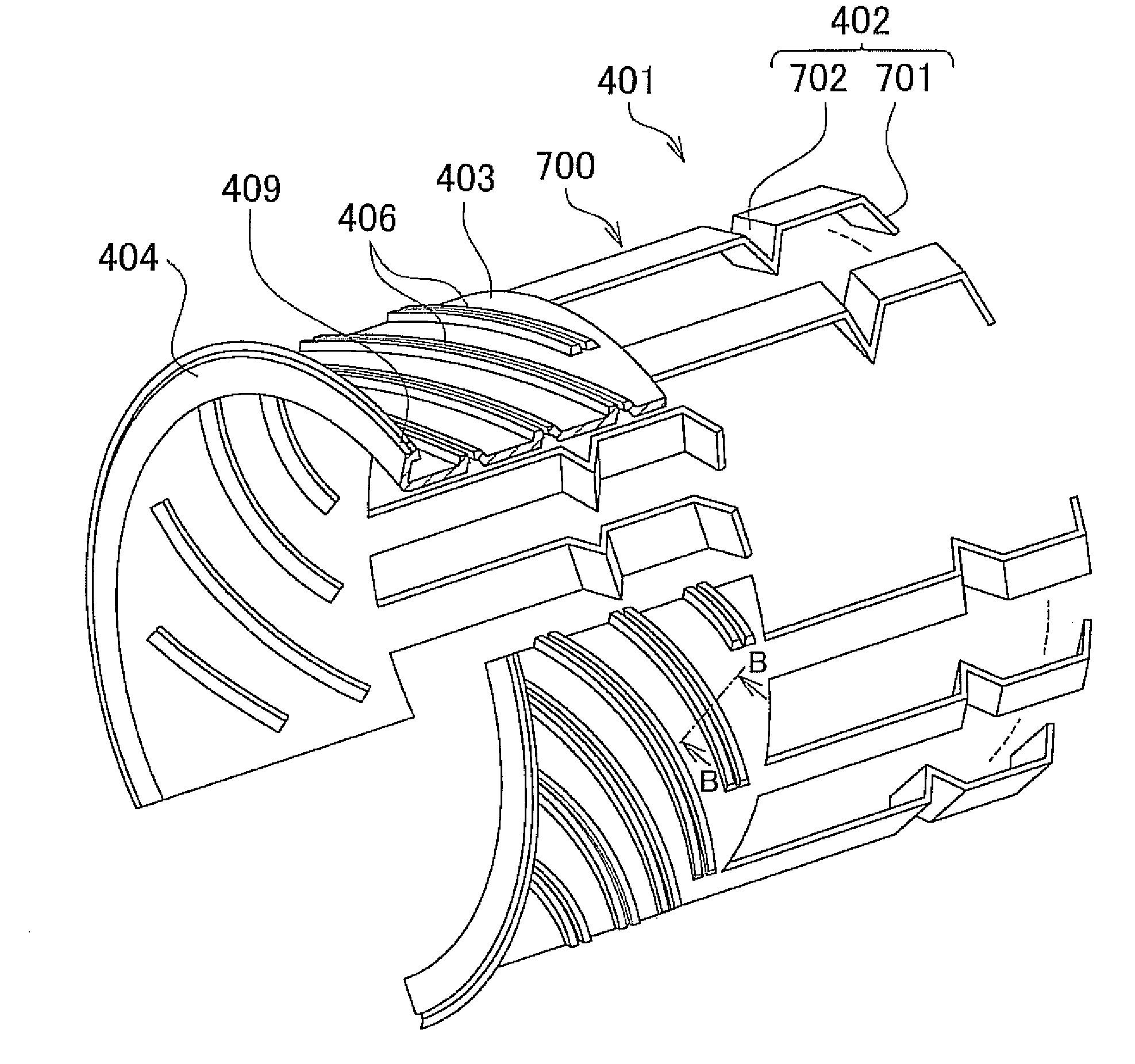
[0087]Next, a third embodiment will be described. FIG. 7 is a longitudinal sectional view showing main parts of the automatic transmission 1 according to the third embodiment of the invention. Referring to FIG. 7, a feature of the automatic transmission 1 according to this embodiment is that the spring 408 of the holding mechanism 402 is provided with a spring action by deforming the tip end portion of the flange portion 405 of the separating / guiding wall 401 into a substantially inverted V shape in an inner diameter direction through pressing or the like. All other consti...

sixth embodiment

[0100]Further, in the example described in the sixth embodiment, the holding mechanism is constituted to restrict axial and rotation movement of the separating / guiding wall by bending the free end portion of the insertion piece of the separating / guiding wall, which is provided with a spring action, in the inner diameter direction to form the first and second bent portions and embedding the fitting space formed between the first and second bent portions in the trough portion in the outer race of the one-way clutch, thereby ensuring that the tip end portion of the insertion piece of the separating / guiding wall is enveloped by the one-way clutch. However, the invention is not limited to this constitution, and the holding mechanism may be constituted to restrict axial and rotation movement of the separating / guiding wall by bending the free end portion of the insertion piece of the separating / guiding wall, which is provided with a spring action, in the inner diameter direction to form th...


PUM


Abstract

An automatic transmission includes a clutch, a clutch drum, a piston, and a brake. The clutch drum, the clutch, and the brake are arranged in sequence in an interior space formed by joining a transmission case to a rear case in an axial direction from the rear case side. A separating / guiding wall that is provided in a circumferential direction so as to define a surplus lubricating oil trapping space for trapping surplus lubricating oil that gathers on an inner peripheral surface of the transmission case and in a second brake, and causes trapped surplus lubricating oil guided thereby into the surplus lubricating oil trapping space to flow downward in the circumferential direction, and a holding mechanism for restricting axial movement of the separating / guiding wall, are provided in relation to spline fitting portions formed on the inner peripheral surface of the transmission case.

Description

INCORPORATION BY REFERENCE[0001]The disclosure of Japanese Patent Application No. 2009-002491 filed on Jan. 8, 2009 including the specification, drawings and abstract is incorporated herein by reference in its entirety.BACKGROUND OF THE INVENTION[0002]1. Field of the Invention[0003]The invention relates to an automatic transmission installed in a vehicle.[0004]2. Description of the Related Art[0005]With regard to a multiple disc clutch used in an automatic transmission for an automobile, Japanese Patent Application Publication No. 10-252777 (JP-A-10-252777), for example, describes the following constitution with which lubricating oil supplied to an inner side of a cylindrical member provided on an inner peripheral side of a multiple disc clutch can be supplied efficiently to a surface of a friction disc by means of a simple structure.[0006]A multiple disc clutch includes an input unit assembly, an output member, first and second friction discs, a pressure plate, a return spring, and...

Claims


Application Information

Patent Timeline
Patent Type & Authority Applications(United States)
IPC IPC(8): F16D13/74F16H57/04
CPCF16D25/0638F16D25/123
Inventor HARASHIMA, TERASUKANEKO, KAZUNORIKOHNO, TETSUYA
Owner TOYOTA JIDOSHA KK
Why Eureka
Try Eureka