Seam welding method and seam welding apparatus

a seam welding and welding method technology, applied in the direction of manufacturing tools, other domestic objects, transportation and packaging, etc., can solve the problems of difficult to achieve a high quality level, process is tedious and time-consuming, difficult to quickly and accurately, etc., to achieve the effect of high quality level and simple and accurate correction of welding tracks

Active Publication Date: 2010-07-08
HONDA MOTOR CO LTD
View PDF0 Cites 15 Cited by
  • Summary
  • Abstract
  • Description
  • Claims
  • Application Information

AI Technical Summary

Benefits of technology

[0010]It is an object of the present invention to provide a seam welding method and a seam welding apparatus which are capable of welding workpieces of various shapes at a high quality level while correcting a welding track more simply and accurately.
[0013]With the above method and apparatus, a load is detected which is imposed along the direction (Y direction) which is perpendicular to the pressing direction (Z direction) along which the electrode rolls press the workpiece at the weld point and the delivering direction (X direction) along which the robot delivers the workpiece at the weld point, and the electrode rolls are turned by an angle depending on the magnitude of the detected load. When the direction along which the electrode rolls deliver the workpiece and the direction along which the robot delivers the workpiece are aligned with each other at the weld point, i.e., when the workpiece is properly welded without the electrode rolls derailing off or biting into the workpiece, the detected load is nil (zero). Therefore, calculations for acquiring a master load and comparing the master load with the detected load are not required. Whether a welding track deviates from a target welding track or not can be determined easily and quickly only based on the detected load, and deviations of the welding track from the target welding track can be corrected appropriately.
[0014]In this aspect, the step of turning the electrode rolls may comprise the steps of acquiring, from a table storing a correspondence relationship between magnitudes of the load and corrective angles for the electrode rolls, one of the corrective angles which corresponds to the magnitude of the detected load, and turning the electrode rolls by the acquired corrective angle. With this arrangement, deviations of the welding track from the target welding track can be corrected more quickly.
[0015]The step of acquiring one of the corrective angles may comprise the step of correcting the corrective angle using one of corrective coefficients established for respective positions in welding regions of the workpiece. With this arrangement, since the corrective angle for the electrode rolls can be determined in view of characteristics such as rigidity at the respective positions in the welding regions of the workpiece, a corrective quantity for the welding track can be adjusted appropriately, so that the workpiece can be welded at a high quality level.

Problems solved by technology

The above process of acquiring a normal torque is disadvantageous in that since the workpiece is welded on a trial basis without the actual welding track correction referred to above, it may be difficult to achieve a high quality level which is good enough to obtain a normal torque.
In addition, the process is tedious and time-consuming because of the need for a plurality of good-quality samples to be produced for increased normal torque accuracy.
When a highly accurate normal torque has not been obtained, it is difficult to quickly and accurately determine whether the actual welding track deviates from a desired normal track or not, with the result that the workpiece cannot be welded at a high quality level.

Method used


Image

  • Seam welding method and seam welding apparatus
  • Seam welding method and seam welding apparatus
  • Seam welding method and seam welding apparatus

Examples


Embodiment Construction

[0037]Seam welding methods according to preferred embodiments of the present invention in reference to seam welding apparatus for carrying out the seam welding methods will be described in detail below with reference to the accompanying drawings.

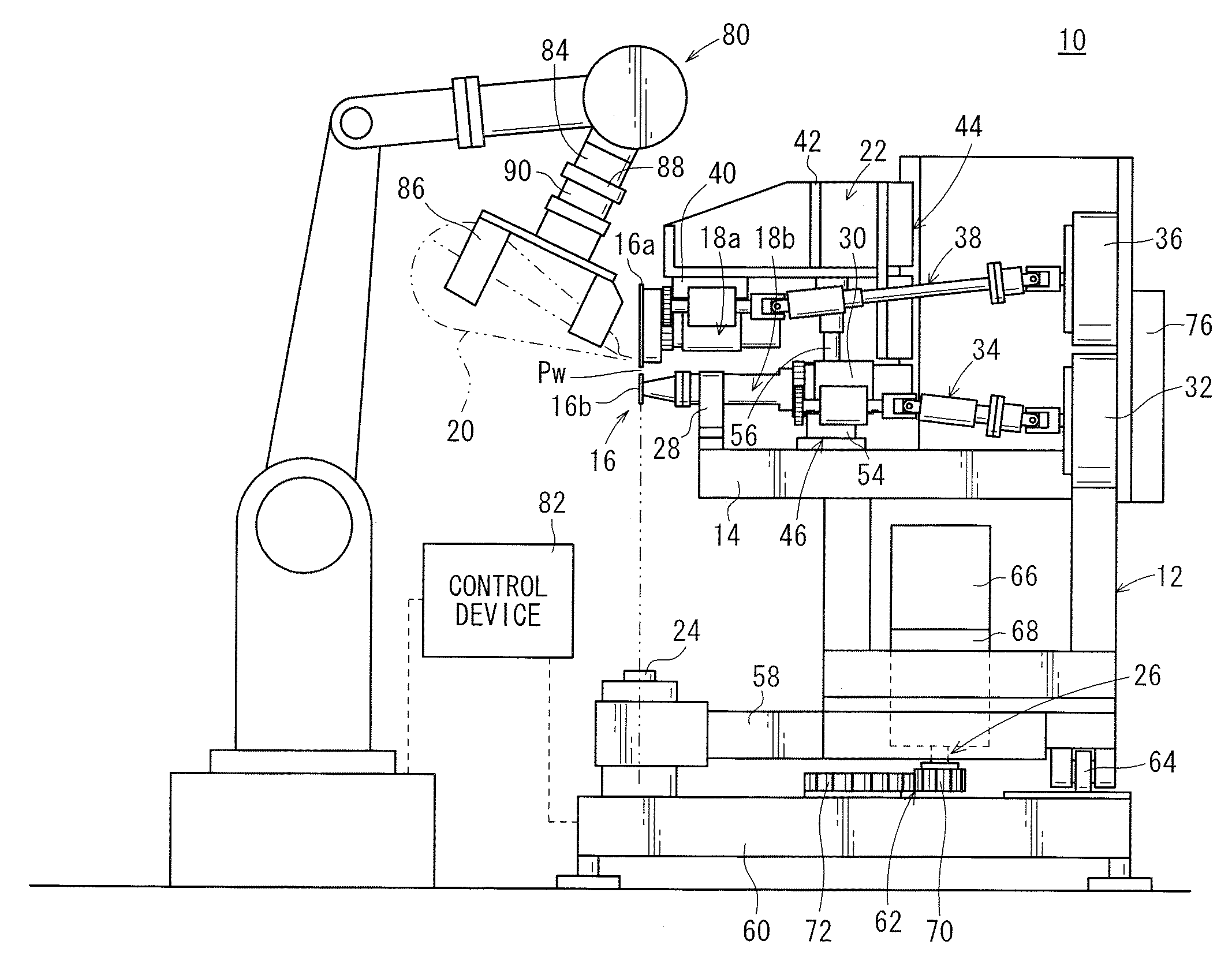
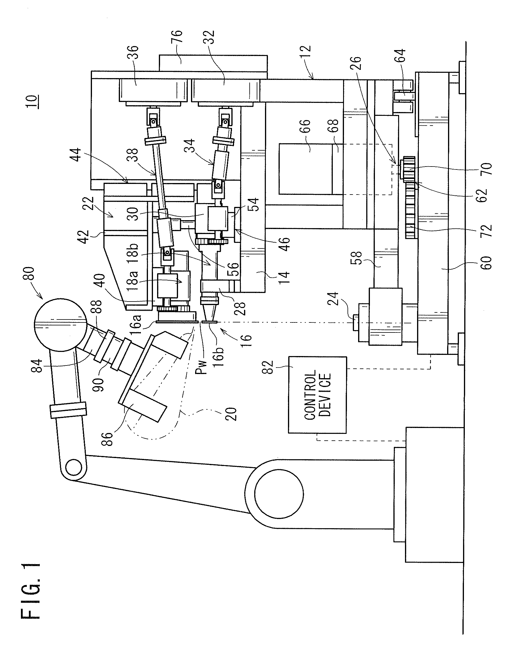
[0038]FIG. 1 shows in plan a seam welding apparatus 10 according to an embodiment of the present invention. The seam welding apparatus 10 serves to resistance-weld a workpiece 20 which comprises, for example, two superposed pressed members (metal members) while delivering the workpiece 20 between a pair of electrode rolls 16a, 16b.

[0039]As shown in FIG. 1, the seam welding apparatus 10 comprises a main body 12 constructed of a plurality of frames, upper and lower electrode mechanisms 18a, 18b mounted on a table 14 of the main body 12 and having an upper electrode roll (electrode roll) 16a and a lower electrode roll (electrode roll) 16b, respectively, a pressing mechanism 22 for pressing a weld region of the workpiece 20 that is sandwiched b...


PUM

PropertyMeasurementUnit
angleaaaaaaaaaa
corrective anglesaaaaaaaaaa
corrective angleaaaaaaaaaa

Abstract

The seam welding apparatus welds a workpiece held by a robot while delivering the workpiece between a pair of electrode rolls. The seam welding apparatus includes a load cell mounted on the robot, for detecting a load imposed along a Y direction which is perpendicular to a pressing direction Z along which the electrode rolls press the workpiece at a weld point and a delivering direction X along which the robot delivers the workpiece at the weld point, a robot controller and an arithmetic unit, a turning mechanism for turning the electrode rolls about the pressing direction Z, and a control device for controlling the turning mechanism to operate depending on the magnitude of the load in the Y direction detected by the load cell.

Description

CROSS-REFERENCE TO RELATED APPLICATION[0001]This application is based upon and claims the benefit of priority from Patent Application No. 2009-001488 filed on Jan. 7, 2009, in the Japan Patent Office, of which the contents are incorporated herein by reference.BACKGROUND OF THE INVENTION[0002]1. Field of the Invention[0003]The present invention relates to a seam welding method and a seam welding apparatus for welding a workpiece while the workpiece is being delivered between a pair of electrode rolls.[0004]2. Description of the Related Art[0005]Fuel tanks for use on motor vehicles or the like, for example, are manufactured by superposing outer circumferential portions of two members that have been pressed to shape and welding the superposed outer circumferential portions. The welded outer circumferential portions have a two-dimensional or three-dimensional curved shape.[0006]For welding workpieces of the type described above, the present applicant has proposed a method of controlling...

Claims


Application Information

Patent Timeline
Patent Type & Authority Applications(United States)
IPC IPC(8): B23K11/08
CPCB23K11/067B23K11/093B23K2101/12B23K2101/006B23K11/255
Inventor KANAYA, KOHEIMACHIDA, HARUOYAMAOKA, NAOJIASAINA, TSUTOMU
Owner HONDA MOTOR CO LTD
Why Eureka
Try Eureka