
Threaded tubular connection which is resistant to bending stresses

Active Publication Date: 2010-07-08
VALLOUREC OIL & GAS FRANCE SAS
View PDF34 Cites 14 Cited by
  • Summary
  • Abstract
  • Description
  • Claims
  • Application Information

AI Technical Summary

Benefits of technology

[0016]A further aim is to provide sealing surfaces between the threaded portions and the outside of the threaded connection which do not constitute a source of cracking due to fretting fatigue.

Problems solved by technology

Drill string components for rotary drilling, in particular drill pipe, heavy weight drill pipe and drill collars, are also subjected to variable bending loads due to rotation of the string when drilling a non-vertical (deviated) borehole and the threaded connections between such components also have to bear and transmit such variable bending loads.
This results in dynamic tensile loads known as repeated loads at the root of the last threads, and more particularly the last male threads, which initiates fatigue cracking at that location leading to catastrophic rupture of the string.
International patent applications WO-A-01 / 75345 and WO-A-01 / 75346 describe solutions for reducing stresses at the roots of said threads, but the resulting improvement may prove insufficient.
Said dynamic loads also cause friction between the parts of the male and female elements in contact, leading to cracking due to fretting fatigue.
However; to form such abutment surfaces, it is necessary to choose thicker tubes or to increase their thickness locally by upsetting, which introduces increased costs.
Separate abutment surfaces are not only unnecessary on such threads, in addition they are undesired as it is difficult to synchronize end of make-up by abutment surfaces and by self-locking threads.

Method used


Image

  • Threaded tubular connection which is resistant to bending stresses
  • Threaded tubular connection which is resistant to bending stresses
  • Threaded tubular connection which is resistant to bending stresses

Examples


Embodiment Construction

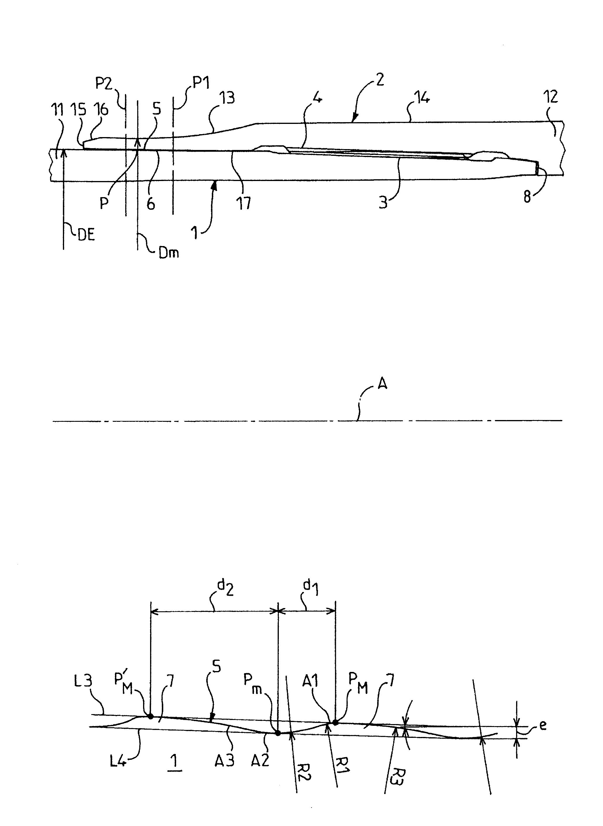
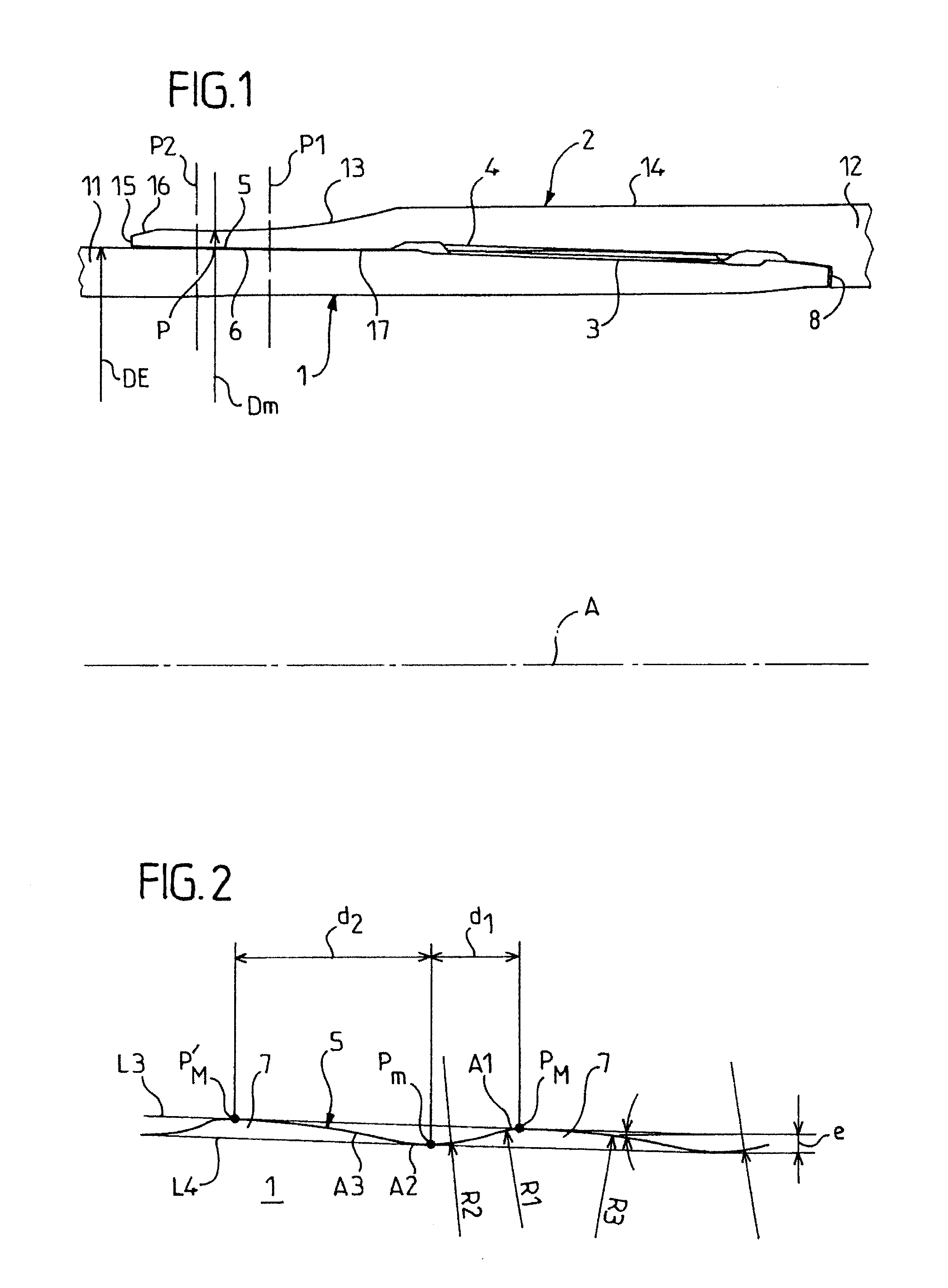
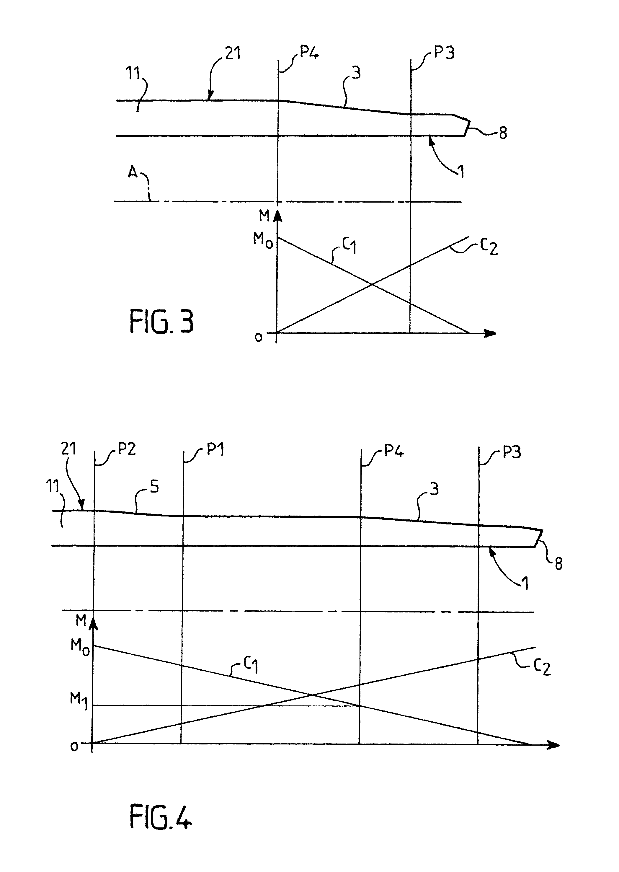
[0086]The threaded tubular connection shown in FIG. 1 comprises a male tubular element 1 and a female tubular element 2 provided with respective tapered threaded portions 3, 4 which cooperate for mutual make up of the two elements. The element 1 is formed at one end of a great length tube 11 and element 2 is formed at one end of a tubular coupling 12 for connecting two tubes similar to 11. A plurality of tubes similar to 11 each one of which has two threaded elements similar to 1 at its ends can then be connected together through couplings similar to 12 each one of which has two threaded elements similar to 2 at its ends to form a string of tubes for an oil well, for example.

[0087]In the example shown, tube 11 has between its two male elements i.e. over the major portion of its length, termed the regular portion, a uniform external diameter ED of 177.8 mm (7 inches) which represents the nominal diameter of the threaded connection. The values for the dimensions given below take this ...


PUM


Abstract

A threaded tubular connection is provided. The connection includes a male tubular element provided with a male threaded portion and a female tubular element provided with a female threaded portion. The male threaded portion and the female threaded portion each include self-locking threads having a crest, a load flank, a stabbing flank and a root, a load flank lead of the self-locking threads being larger than a stabbing flank lead of the self-locking threads such that in a tightened position of the threaded tubular connection, the load flanks and the stabbing flanks of the male self-locking threads are engaged in tight contact with the load flanks and the stabbing flanks of the female self-locking threads. A transfer zone is axially disposed between the threaded portions and a free end of at least one of the tubular elements, while being axially spaced from the threaded portions.

Description

CROSS-REFERENCE TO RELATED APPLICATIONS[0001]The present application is a continuation-in-part of U.S. application Ser. No. 10 / 594,112 and of U.S. application Ser. No. 10 / 558,410. U.S. application Ser. No. 10 / 594,112 was filed on Sep. 25, 2006 and is a national stage application of PCT Application No. PCT / EP05 / 003086, filed Mar. 22, 2005, which claims priority to French Application No. 0403147, filed Mar. 26, 2004. U.S. application Ser. No. 10 / 558,410 was filed on Nov. 28, 2005 and is a national stage application of PCT Application No. PCT / EP04 / 05139, filed May 13, 2004, which claims priority to French Application No. 0306599, filed May 30, 2003. The entire contents of each of these applications are incorporated by reference.BACKGROUND OF THE INVENTION[0002]1. Field of the Invention[0003]The invention relates to a threaded tubular connection for a tubular string which is subjected to dynamic bending loads, comprising a male tubular element provided with a male threaded portion and a...

Claims


Application Information

Patent Timeline
IPC IPC(8): F16L25/00
CPCF16L15/06F16L15/00E21B17/042
Inventor ROUSSIE, GABRIELMASSAGLIA, JACKYGRANGER, SCOTTCARON, OLIVIERVERGER, ERICCONRAD, FRANCOIS
Owner VALLOUREC OIL & GAS FRANCE SAS
Features
  • Generate Ideas
  • Intellectual Property
  • Life Sciences
  • Materials
  • Tech Scout
  • Unparalleled Data Quality
  • Higher Quality Content
  • 60% Fewer Hallucinations
Learn More