
Drive apparatus

a technology of drive apparatus and drive shaft, which is applied in the direction of printers, instruments, and the details of the piezoelectric/electrostrictive device, can solve the problems of large mechanism configured to generate biasing force, difficult to obtain proper drive efficiency, and bulkier magnets. achieve the effect of better drive efficiency

Inactive Publication Date: 2010-07-08
PANASONIC CORP
View PDF21 Cites 26 Cited by
  • Summary
  • Abstract
  • Description
  • Claims
  • Application Information

AI Technical Summary

Benefits of technology

[0024]With the technique shown in FIG. 23B, biasing force is generated by the flat spring 507 disposed opposite the vibration actuator 501, so the flat spring 507 needs to be quite stiff in order to generate a large drive force. However, if the stiffness of the flat spring 507 is increased, the flat spring will not be able to absorb looseness in the direction perpendicular to the sliding direction, and drive efficiency decreases.
[0048]With this drive apparatus, because a movement restrictor is included, the drive generator comes into better contact with the relative drive component. Thus, better drive efficiency can be achieved.

Problems solved by technology

Also, the hole elements 338y and 338x are used for position detection sensors, so a problem is that the magnets end up being bulkier because of the need to ensure linearity in the magnetic flux density with respect to position.
Consequently, the mechanism configured to generate biasing force ends up being larger.
Also, if the biasing force produced by the biasing member 403 is increased in order to generate a larger drive force, the members on which the vibration actuator 401 acts will bend, and the proper drive efficiency will be difficult to obtain.
However, if the stiffness of the flat spring 507 is increased, the flat spring will not be able to absorb looseness in the direction perpendicular to the sliding direction, and drive efficiency decreases.

Method used


Image

  • Drive apparatus
  • Drive apparatus
  • Drive apparatus

Examples


first embodiment

[0073]The drive apparatus in a first embodiment will be described.

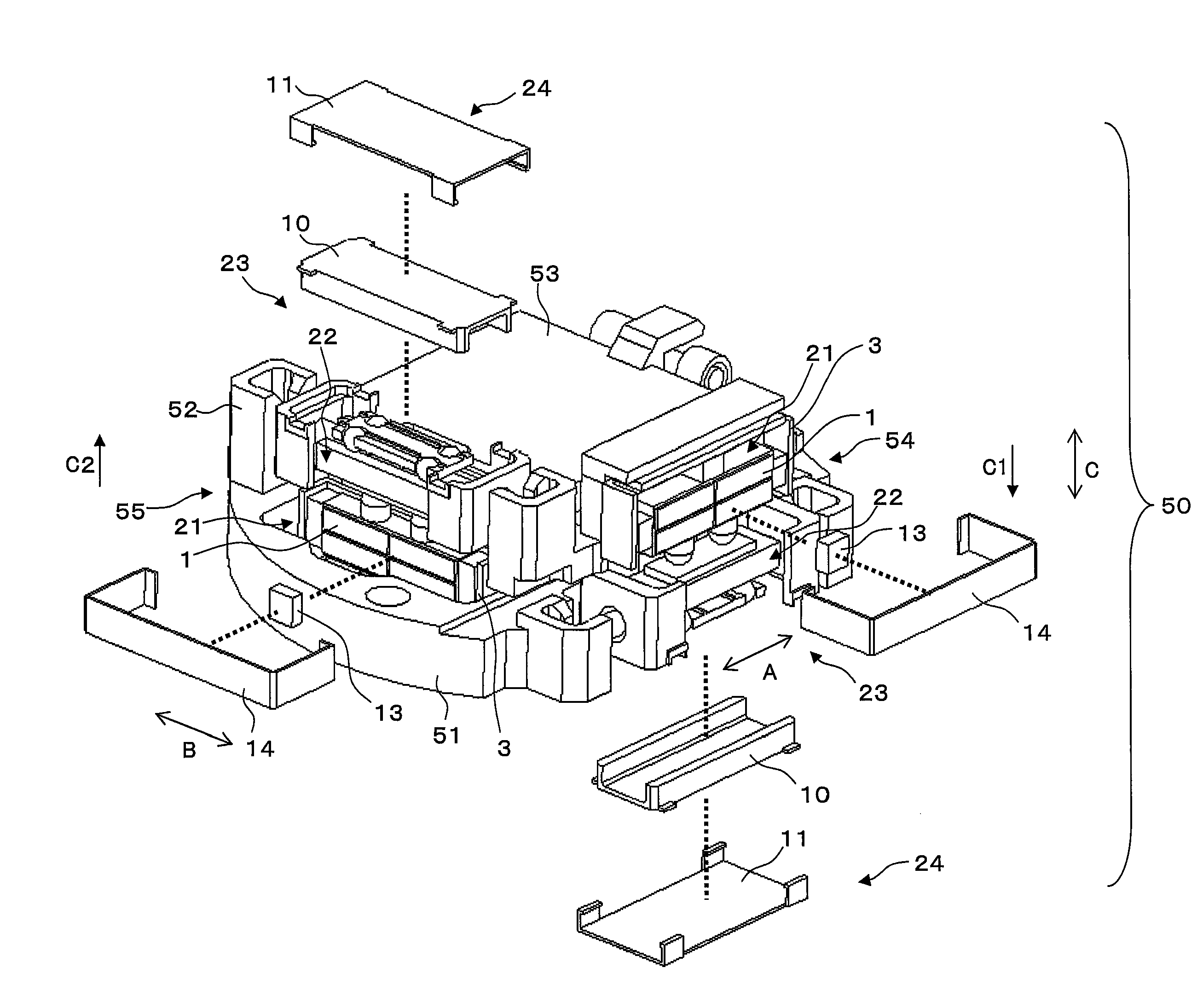
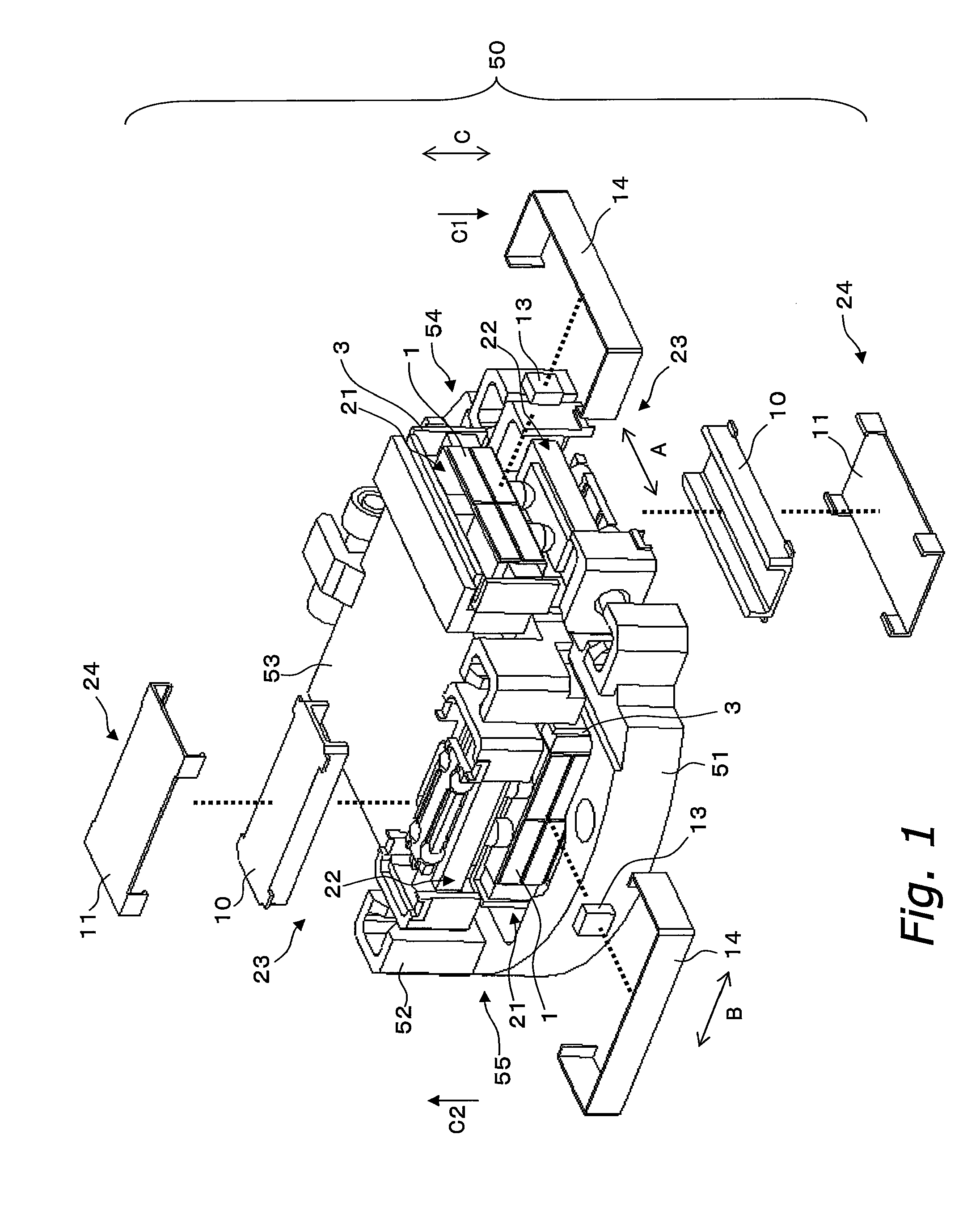
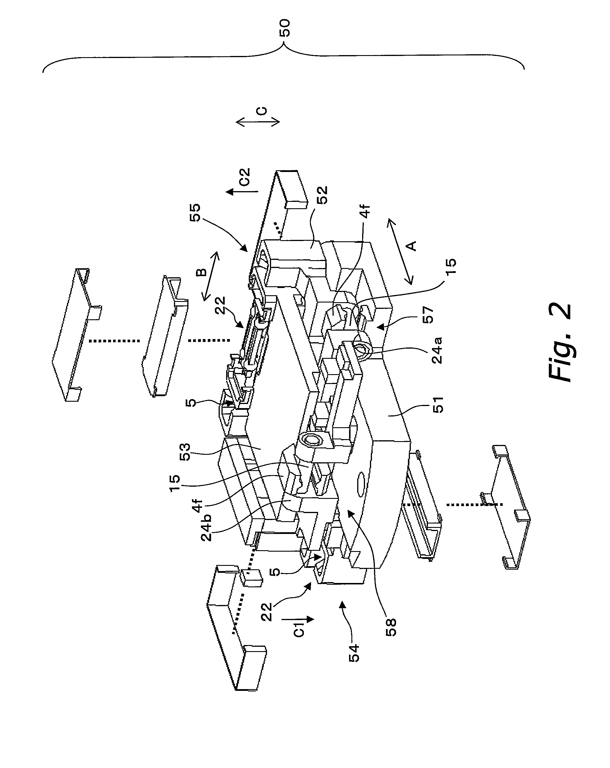
[0074]FIG. 1 is an exploded oblique view of a drive apparatus 50, and FIG. 2 is an exploded oblique view of the back side of the drive apparatus 50.

Drive Apparatus 50

[0075]The drive apparatus 50 is installed in a digital still camera, a digital video camera, or another such optical device, and is used to drive an optical component such as a lens or a CCD, a CMOS, or another such imaging element in two directions perpendicular to the optical axis, to correct blurring of an optical image. The drive apparatus 50 shown in FIG. 1 in particular is an apparatus that has an imaging element, etc., mounted on its upper face side, and drives this element.

[0076]As shown in FIG. 1, the drive apparatus 50 comprises a first frame 51, a second frame 52, a third frame 53, a first drive mechanism 54, and a second drive mechanism 55. The second frame 52 is supported movably in a first direction A with respect to the first frame 51. The ...

second embodiment

[0144]The drive apparatus in a second embodiment will be described. The constitution that is the same as that described for the first embodiment is numbered the same, and its description will be omitted.

[0145]Drive Apparatus 60

[0146]The drive apparatus 60 shown in FIG. 10 is installed in a digital still camera, a digital video camera, or another such optical device, and is used to drive an optical component such as a lens or a CCD, a CMOS, or another such imaging element in two directions perpendicular to the optical axis, to correct blurring of an optical image. The drive apparatus 60 shown in FIG. 10 in particular is an apparatus that has an imaging element, etc., mounted on its upper face side, and drives this element.

[0147]As shown in FIG. 10, the drive apparatus 60 comprises a first frame 61, a second frame 62, a third frame 63, a first drive mechanism 64, and a second drive mechanism 65, The second frame 62 is supported movably in a first direction A with respect to the first ...

third embodiment

[0164]The drive apparatus in a third embodiment will be described.

[0165]FIG. 12 is an exploded oblique view of the drive apparatus 120 in a third embodiment.

[0166]The drive apparatus 120 includes a drive generator 121, a sliding member (relative drive component) 122, a bearing (restrictor) 123, a biaser 124, and a main body 125.

[0167]The drive generator 121 generates drive with a piezoelectric element or another such electro-mechanical conversion element, for example. The sliding member 122 receives the drive generated by the drive generator 121, and is driven relative to the drive generator 121. The bearing 123 is disposed opposite the drive generator 121 with the sliding member 122 interposed therebetween, and restricts displacement of the sliding member 122 to the opposite side from the drive generator 121 side where the drive generator 121 acts on the sliding member 122. The biaser 124 biases the drive generator 121 and the bearing 123 in the direction of moving closer together....


PUM


Abstract

A drive apparatus includes a first frame, a second frame, a third frame, a first drive mechanism, and a second drive mechanism. The second frame is supported movably in a first direction with respect to the first frame. The third frame is supported movably in a second direction that intersects the first direction with respect to the second frame. The first drive mechanism is provided between the first frame and the second frame, and configured to move the first frame and the second frame relative to each other. The second drive mechanism is provided between the second frame and the third frame, and configured to move the second frame and the third frame relative to each other. Each of the first drive mechanism and the second drive mechanism has a drive generator configured to generate drive with a piezoelectric element, and a drive receiver that is pressed relative to the drive generator and receive the drive generated by the drive generator. An action direction in which the drive generator acts on the drive receiver in the first drive mechanism is parallel and opposite to an action direction in which the drive generator acts on the drive receiver in the second drive mechanism.

Description

CROSS-REFERENCE TO RELATED APPLICATIONS[0001]This U.S. National stage application claims priority under 35 U.S.C. §119(a) to Japanese Patent Applications No. 2006-230248 filed in Japan on Aug. 28, 2006 and No. 2006-241946 filed in Japan on Sep. 6, 2006, the entire contents of which are hereby incorporated herein by reference.BACKGROUND[0002]1. Technical Field[0003]The technical field to a drive apparatus, and more particularly relates to a drive apparatus equipped with a drive generator for generating drive.[0004]2. Description of the Related Art[0005]Example of conventional vibration actuators for generating vibration are given in Japanese Laid-Open Patent Applications JPH11-271480 and JP2000-32785, in which electrodes are provided at four places on a piezoelectric element, AC voltages of different phase are applied to two pairs of diagonally opposite electrodes, and longitudinal vibration and curved vibration are generated harmonically in the piezoelectric element, which yields a ...

Claims


Application Information

Patent Timeline
Patent Type & Authority Applications(United States)
IPC IPC(8): H01L41/04H01L41/09
CPCG02B27/646G03B5/00G03B2205/0007H02N2/004H02N2/026H02N2/028H04N5/2254H04N5/23264G03B2205/0061H04N23/682
Inventor MUKAE, HIDEAKI
Owner PANASONIC CORP
Learn More