This helps you quickly interpret patents by identifying the three key elements:
Problems solved by technology
Method used
Benefits of technology
Benefits of technology
[0020]According to the present invention, the illuminating device can be provided, which has a simple structure, excellent uniformity in light emission without producing unevenness or rings in color or brightness on the irradiation face, and excellent property in color rendering.
Problems solved by technology
However, in the structures described in Patent Documents 1 and 2, the illuminating devices are complicated because they have extra lens and shading member with a specific structure.
Method used
Image
Click on the blue label to locate the original text in one second.
Reading with bidirectional positioning of images and text.
Examples
embodiment 1
[1-5-1] Embodiment 1
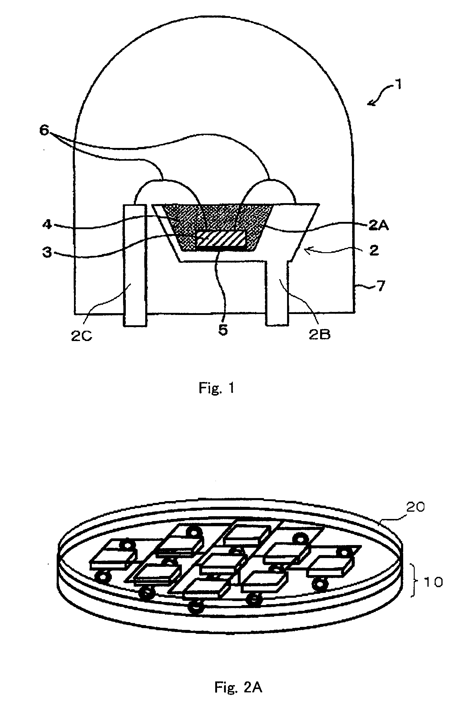
[0179]FIG. 1 schematically shows a configuration of an LED lamp according to one embodiment of the present invention.
[0180]LED lamp 1 according to this embodiment contains frame 2, LED 3 as a light-emitting element and phosphor-containing part 4 which partly absorbs a light emitted from LED 3 and emits a light with a different wavelength.
[0181]Frame 2 is a metal base for holding LED 3 and phosphor-containing part 4. Frame 2 has a pair of conductive members 2B, 2C, and in the upper surface of one conductive member 2B, there is formed concave (recess) 2A opening upward in FIG. 1 with a trapezoidal cross section.
[0182]LED 3 is placed in the bottom of concave 2A as the light-emitting element. LED 3 emits a light in the region of near-ultraviolet to blue while being supplied with electric power and may be as described in [1-1]. Furthermore, in concave 2A, LED 3 is covered with phosphor-containing part 4 which partly absorbs the light emitted from LED 3 and emits a lig...
embodiment 2
[1-5-2] Embodiment 2
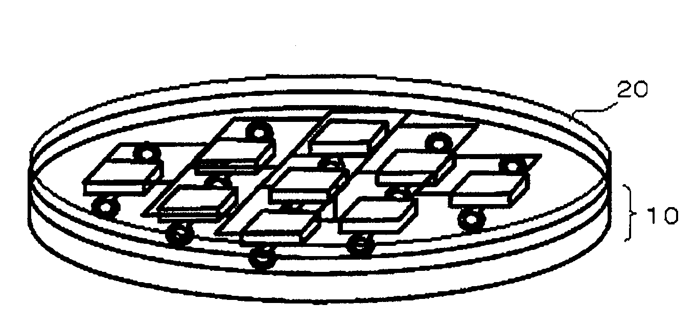
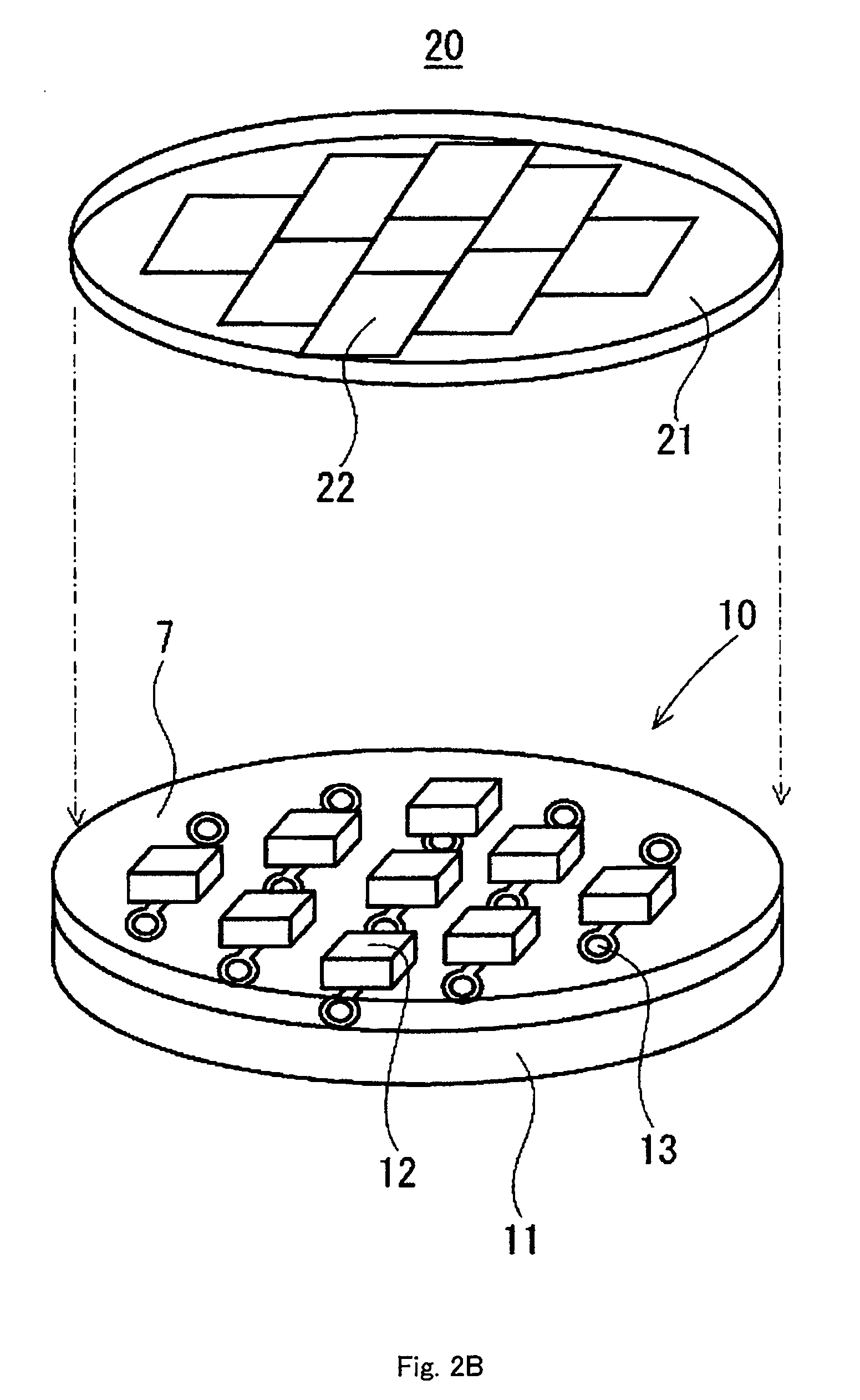
[0189]Although Embodiment 1 illustrates an example of constituting the solid light-emitting element and the phosphor as a single module by sealing LED 3 by phosphor-containing part 4, the solid light-emitting element and the phosphor may be constituted as separate modules. There will be described a luminescence source of Embodiment 2 where a solid light-emitting element and a phosphor are constituted.
[0190]The luminescence source shown in FIG. 2A has solid light-emitting element module 10 which is a solid light-emitting element formed as a module and phosphor module 20 which is a phosphor-containing part formed as a module. As shown in FIG. 2B, phosphor module 20 is joined to solid light-emitting element module 10 to provide the luminescence source. There will be described each module.
[0191]As shown in FIG. 2B, solid light-emitting element module 10 has base 11 and solid light-emitting element 12 disposed on base 11.
(i...
example 1
[E1-2-1] Example 1, Comparative Example 1
[0273]Blue, green and red phosphors described below were used.
[0274]Blue phosphor (B1): Ba0.7Eu0.3MgAl10O17, a peak wavelength of a major emission peak: 457 nm, a weight median size: 11 μm.
[0275]Green phosphor (G1): Ba1.39Sr0.46Eu0.15SiO4, a peak wavelength of a major emission peak: 525 nm, a weight median size: 20 μm.
[0276]Red phosphor (R1): Sr0.792Eu0.008Ca00.2AlSiN3, a peak wavelength of a major emission peak: 628 nm, a weight median size: 9 μm.
PUM
Abstract
An illuminating device has a solid light-emitting element module (10) and a phosphor module (20) joined to the solid light-emitting element module (10). The solid light-emitting element module (10) has a plurality of the solid light-emitting elements. The phosphor module (20) has a plurality of phosphor-containing parts (22) corresponding to the individual solid light-emitting elements (12). Thus, a light-emitting part is provided, which has more than one kind of luminescence sources having the solid light-emitting element (12) and the phosphor-containing part (22). An illumination intensity of a composite light is 150 lux or more at a distance of 30 cm perpendicularly from the light-emitting surface of the light-emitting part.
Description
TECHNICAL FIELD[0001]The present invention relates to an illuminating device emitting composite light. In particular, the invention relates to an illuminating device comprising integrated luminescence sources having a light-emitting element and a phosphor, emitting a composite light of primary lights from the luminescence sources.BACKGROUND ART[0002]In the past, a variety of devices such as fluorescent lamps have been used as a white illuminating device. Recently, there have been developed new light sources such as inorganic ELs (Electro Luminescence), organic ELs (OEL (Organic Electro Luminescence) and OLEDs (Organic Light Emitting Diode)) and semiconductor light-emitting elements, which have been used for developing an illuminating device. For example, for an illuminating device such as an LED lamp using a semiconductor light-emitting element, the surface of the semiconductor light-emitting element is coated with a phosphor, or powder of the phosphor is contained in a resin consti...
Claims
Application Information
Patent Timeline
Application Date:The date an application was filed.
Publication Date:The date a patent or application was officially published.
First Publication Date:The earliest publication date of a patent with the same application number.
Issue Date:Publication date of the patent grant document.
PCT Entry Date:The Entry date of PCT National Phase.
Estimated Expiry Date:The statutory expiry date of a patent right according to the Patent Law, and it is the longest term of protection that the patent right can achieve without the termination of the patent right due to other reasons(Term extension factor has been taken into account ).
Invalid Date:Actual expiry date is based on effective date or publication date of legal transaction data of invalid patent.

