Process and apparatus for switching large-area electrochromic devices

a technology of electrochromic devices and process, applied in the direction of optics, non-linear optics, instruments, etc., can solve the problem that it is normally not possible to measure the potential difference between the electrode layers directly, and achieve the effects of limiting cell current, maximum lifetime, and optimizing transmission homogeneity

Active Publication Date: 2010-07-08
ECONTROL GLAS
View PDF9 Cites 120 Cited by
  • Summary
  • Abstract
  • Description
  • Claims
  • Application Information

AI Technical Summary

Benefits of technology

[0027]It was found that the relationship between the applied contact potential and the maximum potential difference generated between the electrode layers may be described by a simple equation, involving cell current and a constant resistance. This resistance is only dependent on cell width and height and on material properties of the electrode layer. This resistance is almost independent of temperature, hence is unaffected by electrolyte conductivity. This is advantageous, because it is not necessary to know the electrolyte conductivity in order to ensure that safe potentials are generated between the electrode layers.

Problems solved by technology

Unfortunately, it is not normally possible to measure the potential difference between the electrode layers directly, because the two electrode contacts are on opposite sides of the cell.

Method used


Image

  • Process and apparatus for switching large-area electrochromic devices
  • Process and apparatus for switching large-area electrochromic devices
  • Process and apparatus for switching large-area electrochromic devices

Examples


examples

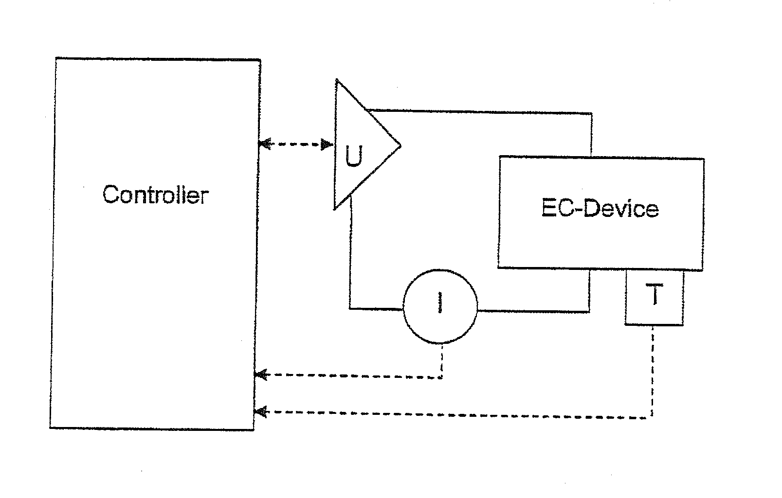
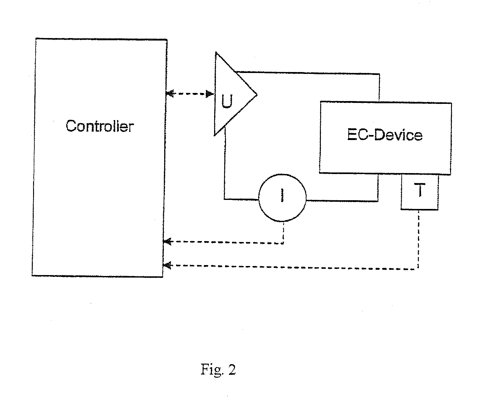
[0063]The invention will be further explained using as example the switching of a 40×80 cm2 electrochromic device, from a completely bleached to coloured state. Before switching begins, the relevant parameters are saved in the memory of the controller. The relevant parameters are as follows:[0064]1. Electrochromic device height (length of contacted edges)=40 cm[0065]2. Electrochromic device width (length of non-contacted edges)=80 cm[0066]3. Resistance constant for electrode layers (k)=10 Ohm[0067]4. Maximum current density (jmax)=33.3 μA / cm2, as calculated according

jmax=(QmaxTime)=20600smCcm2=33,3μAcm2,[0068]where (Qmax) is the maximum charge density corresponding to the completely coloured state and (Time) is the desired switching time.[0069]5. The maximum current (imax) is calculated according to

imax=(j×Area)+(T-T0)×F=(33,3μAcm2×3200cm2)+(T-T0)×F=107mA,[0070]assuming F=0 in this example, for sake of simplicity.[0071]6. Safe coloration potential limit (Uec, col)=+3.00 V at 0° C.[0...


PUM

PropertyMeasurementUnit
temperaturesaaaaaaaaaa
areaaaaaaaaaaa

Abstract

A method is disclosed for controlling switching of an electrochromic device comprising at least the following components: a first and a second electrode layer, a first and a second layer in which ions can be reversibly intercalated, and a transparent ion-conducting layer. At least one of the layers in which ions may be reversibly inserted is electrochromic. The optical properties of the device are modified when a potential is applied between the electrode layers. The potential applied is limited such that the maximum generated potential difference never exceeds the safe redox limits, and that the current does not exceed some predetermined limit. Switching of electrochromic devices in this manner allows for maximum device lifetime, while simultaneously optimising switching speed and transmission homogeneity. The method is characterised in that the potential applied to the electrode layers is varied in the form of a stepped ramp, during which time the current is measured constantly.

Description

FIELD OF THE INVENTION[0001]The present invention relates to a method and a system for switching a large-area electrochromic device. In particular, the invention concerns a method capable of switching electrochromic devices in a manner which ensures that safe electrical potentials are applied, while simultaneously optimising switching speed and homogeneity of optical transmission.BACKGROUND OF THE INVENTION[0002]Electrochromic materials undergo a change in optical properties when ions and electrons are inserted into them under the influence of an electric field. An electrochromic device may be constructed from such materials, such that the visual transmittance of said device changes when an electrical potential is applied between two electrodes. Electrochromic devices have many applications, including switchable glazings (where transmission of heat and light is regulated according to some scheme), automotive mirrors (where mirrors switch to prevent the driver from being dazzled by g...

Claims


Application Information

Patent Timeline
Patent Type & Authority Applications(United States)
IPC IPC(8): G02F1/163
CPCG02F1/163
Inventor MATTHEWS, JEREMY
Owner ECONTROL GLAS
Why Eureka
Try Eureka