Loudspeaker with rear surround support

a technology of rear surround and loudspeaker, which is applied in the direction of transducer details, electrical transducers, plane diaphragms, etc., can solve the problem of the proportion of exposed front mechanical components emitted by sound

Inactive Publication Date: 2010-07-08
CAMPBELL JACK BLAINE
View PDF6 Cites 12 Cited by
  • Summary
  • Abstract
  • Description
  • Claims
  • Application Information

AI Technical Summary

Benefits of technology

[0004]In one exemplary embodiment, the invention comprises an improved dynamic loudspeaker that eliminates all visible mechanical components except the diaphragm when viewed from the front in a mounting baffle, and that enables all of the front exposed diaphragm surface to emit sound. By using a surround support entirely located within the rear perimeter edge of the diaphragm, and a conventional dynamic loudspeaker motor / driver and voice coil system sized to fit behind and entirely inside the perimeter edge of the acoustic diaphragm, the invention permits the entire diaphragm to visually fill an opening in a mounting baffle and emit sound.

Problems solved by technology

Further, conventional dynamic loudspeaker construction using a perimeter-located surround support results in only a portion of the exposed front mechanical components to emit sound.

Method used


Image

  • Loudspeaker with rear surround support
  • Loudspeaker with rear surround support
  • Loudspeaker with rear surround support

Examples


Embodiment Construction

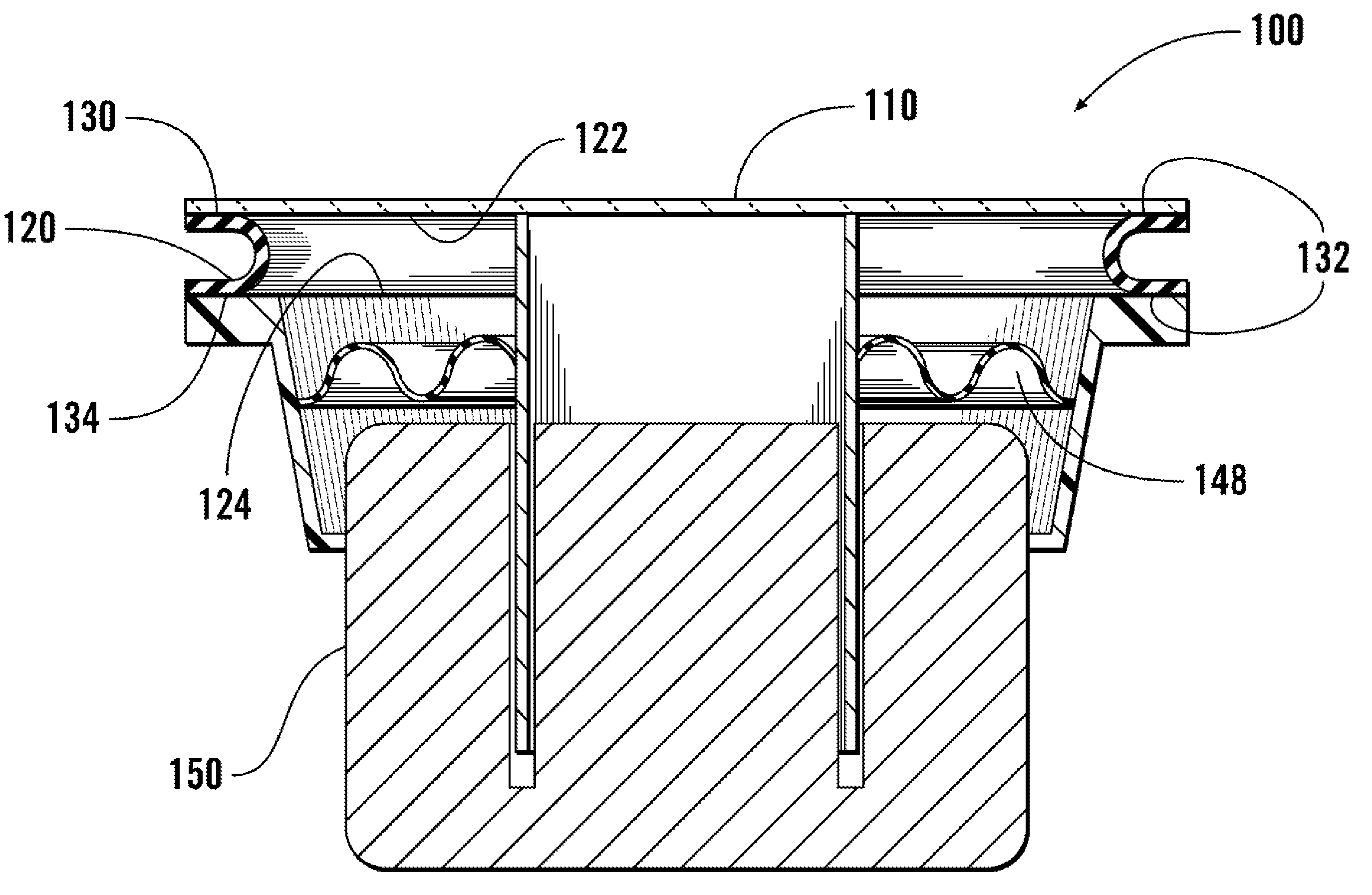
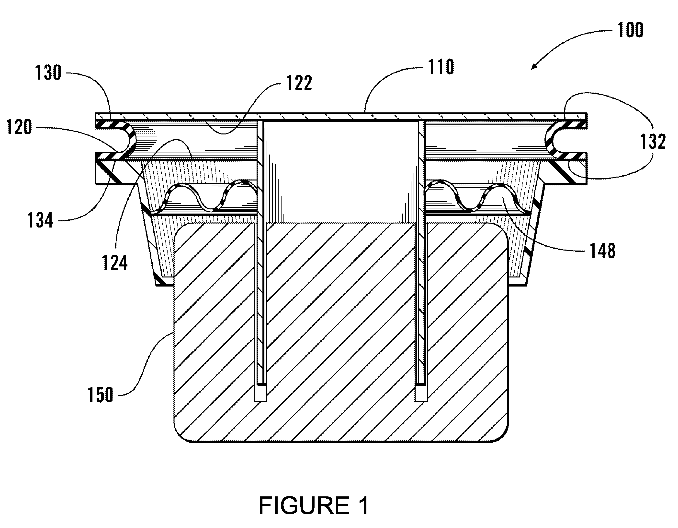
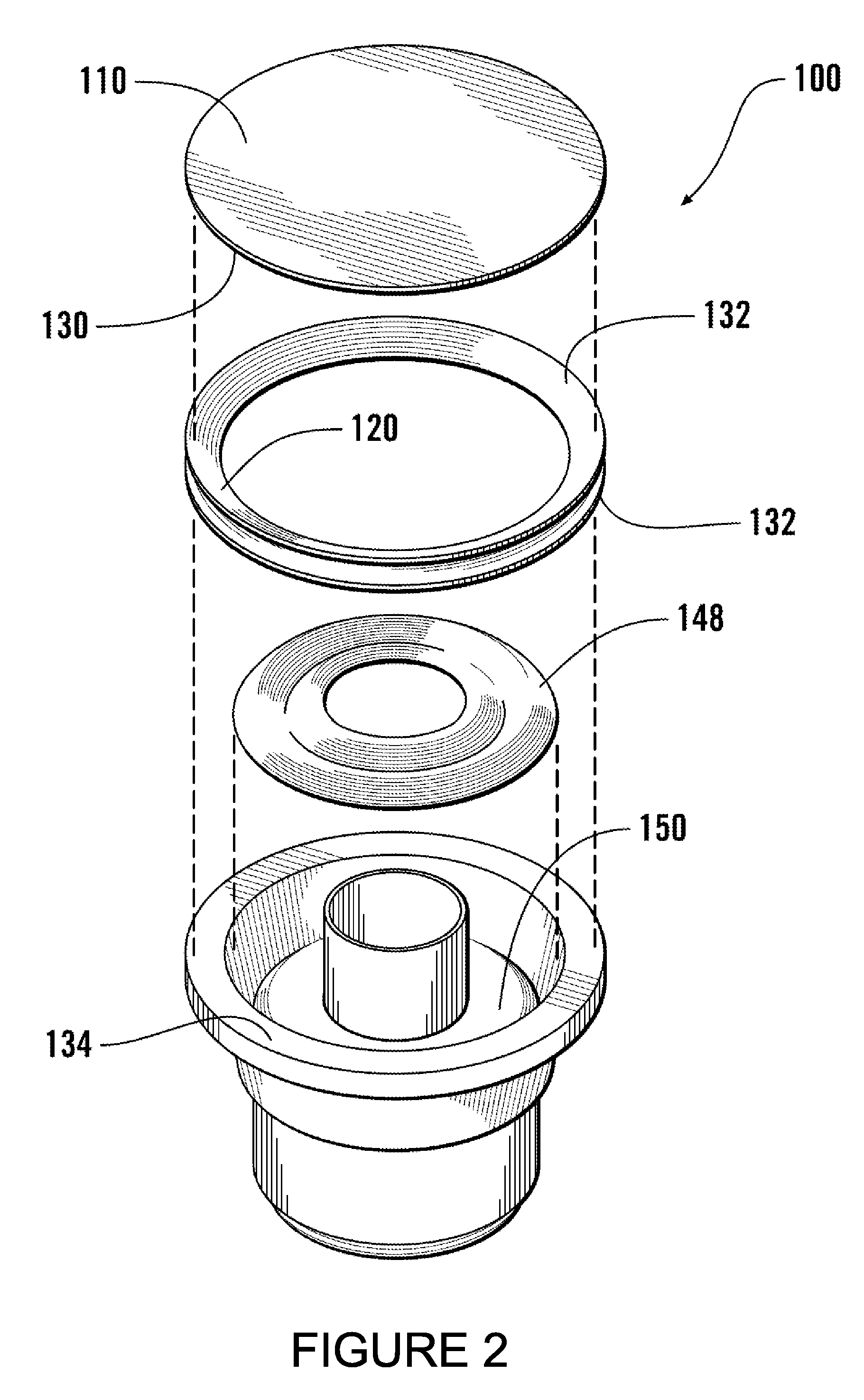
[0007]In one exemplary embodiment, as shown in FIGS. 1 and 2, an acoustic loudspeaker 100 comprises an acoustic diaphragm 110 supported on one side by surround support 120. The surround support 120 may be flexible, and may be made of rubber, plastic, paper, or similar material, or some combination thereof. The surround support 120 may be ring-shaped with an open center, and may comprise a solid band, or, as shown in FIGS. 1 and 2, may comprise a U-shape or V-shape when view in cross-section, with two mating surfaces 132, 134. The diaphragm mating surface 132 is affixed to the diaphragm 110 forming an upper joint 122, while the driver mating surface 134 is affixed to the driver 150 forming a lower joint 124. A flexible baffle 148 may located under the surround support, supported by the driver 150.

[0008]As shown, the outer circumference of the surround support should not extend beyond the edge of the diaphragm, and the surround support may be equal in diameter or, in fact, have a slig...


PUM


Abstract

An improved dynamic loudspeaker that eliminates all visible mechanical components except the diaphragm when viewed from the front in a mounting baffle, and enables all of the front exposed diaphragm surface to emit sound. The surround support is entirely located within the perimeter edge of the diaphragm. A conventional dynamic loudspeaker motor / driver and voice coil system sized to fit behind and entirely inside the perimeter edge of the acoustic diaphragm permits the entire diaphragm to visually fill an opening in a mounting baffle and emit sound.

Description

[0001]This application claims benefit of and priority to U.S. Provisional Application No. 61 / 204,099, entitled “LOUDSPEAKER WITH REAR UNDERHUNG SURROUND SUPPORT,” filed Dec. 31, 2008, by Jack Blaine Campbell, and is entitled to that filing date for priority. The specification, figures and complete disclosure of U.S. Provisional Application No. 61 / 204,099 are incorporated herein by specific reference for all purposes.FIELD OF INVENTION[0002]This invention relates to an improved loudspeaker assembly.BACKGROUND OF INVENTION[0003]Existing dynamic loudspeakers have some portion of the outermost mechanism existing outside the perimeter of the sound producing diaphragm. This is due to the use of flexible surround supports attached to the outermost perimeter edge of the diaphragm, thus requiring that some portion of either a housing or the surround support be viewable from the front when such a loudspeaker is mounted onto a baffle. Decorative grille coverings are often used to hide the expo...

Claims


Application Information

Patent Timeline
Patent Type & Authority Applications(United States)
IPC IPC(8): H04R1/00
CPCH04R7/04H04R7/20H04R2307/207H04R2307/204H04R2231/003
Inventor CAMPBELL, JACK BLAINE
Owner CAMPBELL JACK BLAINE
Why Eureka
Try Eureka