
Image processing device, image processing method, image processing program, recording medium with image processing program recorded therein, and image processing processor

Active Publication Date: 2010-07-08
PANASONIC INTELLECTUAL PROPERTY CORP OF AMERICA +1
View PDF5 Cites 24 Cited by
  • Summary
  • Abstract
  • Description
  • Claims
  • Application Information

AI Technical Summary

Benefits of technology

[0010]The image processing device having the above-stated structure: divides an input image into a plurality of areas; determines what kind of directional characteristic a texture (luminance change) that exists in each divided area has; selects, based on the judgment, one or more areas in each of which the texture has a unidirectional characteristic; and estimates a tilt angle of the captured image based on the selected areas.
[0011]The texture is a pattern formed as a group of pixels having a large edge strength in the captured image. The texture that exists in an area has a unidirectional characteristic when most of the line segments included in the area that have each been formed by connecting adjacent pixels having large edge strengths are oriented substantially in one direction. The texture is obtained by performing calculation with use of pairs of positions and luminances each relating to a corresponding one of the pixels included the captured image. When the texture that exists in the area has a unidirectional characteristic, the edge of the structural objects such as a building is considered to be included in the area. Also, the edge of the structural object is highly likely to be oriented in a horizontal or vertical direction. In such a way, the image processing device estimates the tilt angle of the captured image by analyzing pixel information pieces such as luminances in the areas.
[0012]Accordingly, if one or more of the plurality of divided areas are areas in each of which most of the line segments are oriented in the same direction, it is possible to estimate the tilt angle of the captured image based on such areas even if these areas do not exist in the upper part of the captured image. The image processing device selects only one or more areas in each of which most of the line segments are oriented in the same direction in the captured image regardless of whether or not these areas exist in the upper part of the captured image, and excludes, in advance, one or more areas in each of which the line segments are randomly oriented. Therefore, the image processing device is capable of correctly estimating the tilt angle of the captured image, and correcting the tilt of the captured image even if areas that are suitable for estimating the tilt angle of the captured image and areas that are not suitable for estimating the tilt angle of the captured image exist together in the captured image.
[0013]The judgment unit may calculate directional distributions of luminance gradients.
[0014]Since the image processing device is capable of recognizing line segments included in the captured image and the directions in which the line segments are oriented as the luminance change and directions in which the luminance changes (i.e. luminance gradients), respectively, the image processing device is capable of determining what proportion of the line segments is oriented in the same direction based on the directional distribution of the luminance gradients.
[0015]The judgment unit may calculate a directional distribution of intensities of luminance spectrums.

Problems solved by technology

However, it is problematic that, due to a usage act that the wearable terminal keeps on capturing images while being worn by the user at all times, the qualities of the captured images notably deteriorate because of a motion of the user.
In particular, it is problematic that when images are captured with the wearable terminal tilting off the horizontal, the captured images are tilted.
Therefore, when the image is captured with the user standing substantially straight, it is expected that it is difficult to estimate a horizontal direction based on line segments that exist in a lower part of the captured image due to an influence by a ground and a shadow, while it is easy to estimate the horizontal direction based on line segments of structural objects and the like that exist in the upper part of the captured image.

Method used


Image

  • Image processing device, image processing method, image processing program, recording medium with image processing program recorded therein, and image processing processor
  • Image processing device, image processing method, image processing program, recording medium with image processing program recorded therein, and image processing processor
  • Image processing device, image processing method, image processing program, recording medium with image processing program recorded therein, and image processing processor

Examples


Embodiment Construction

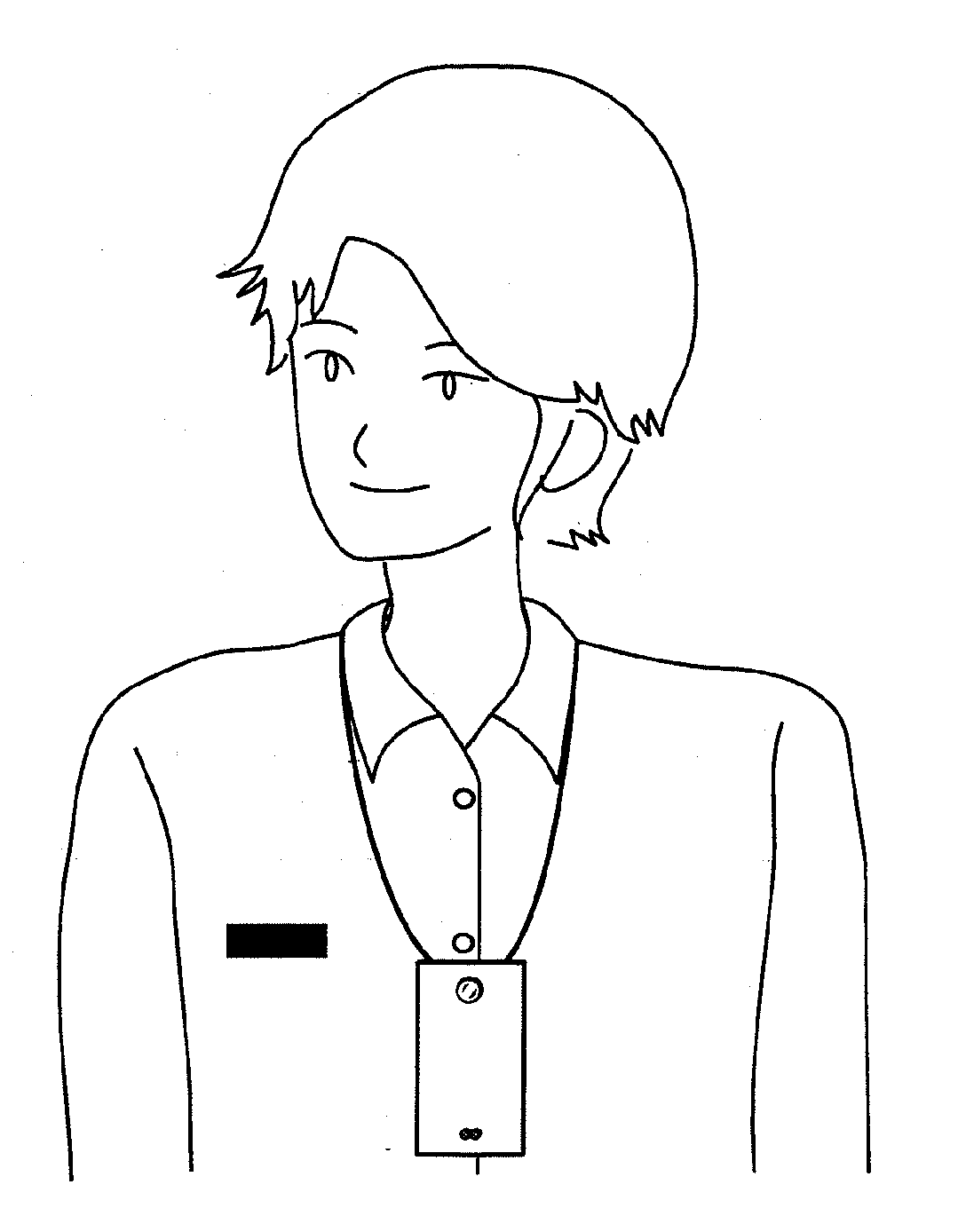
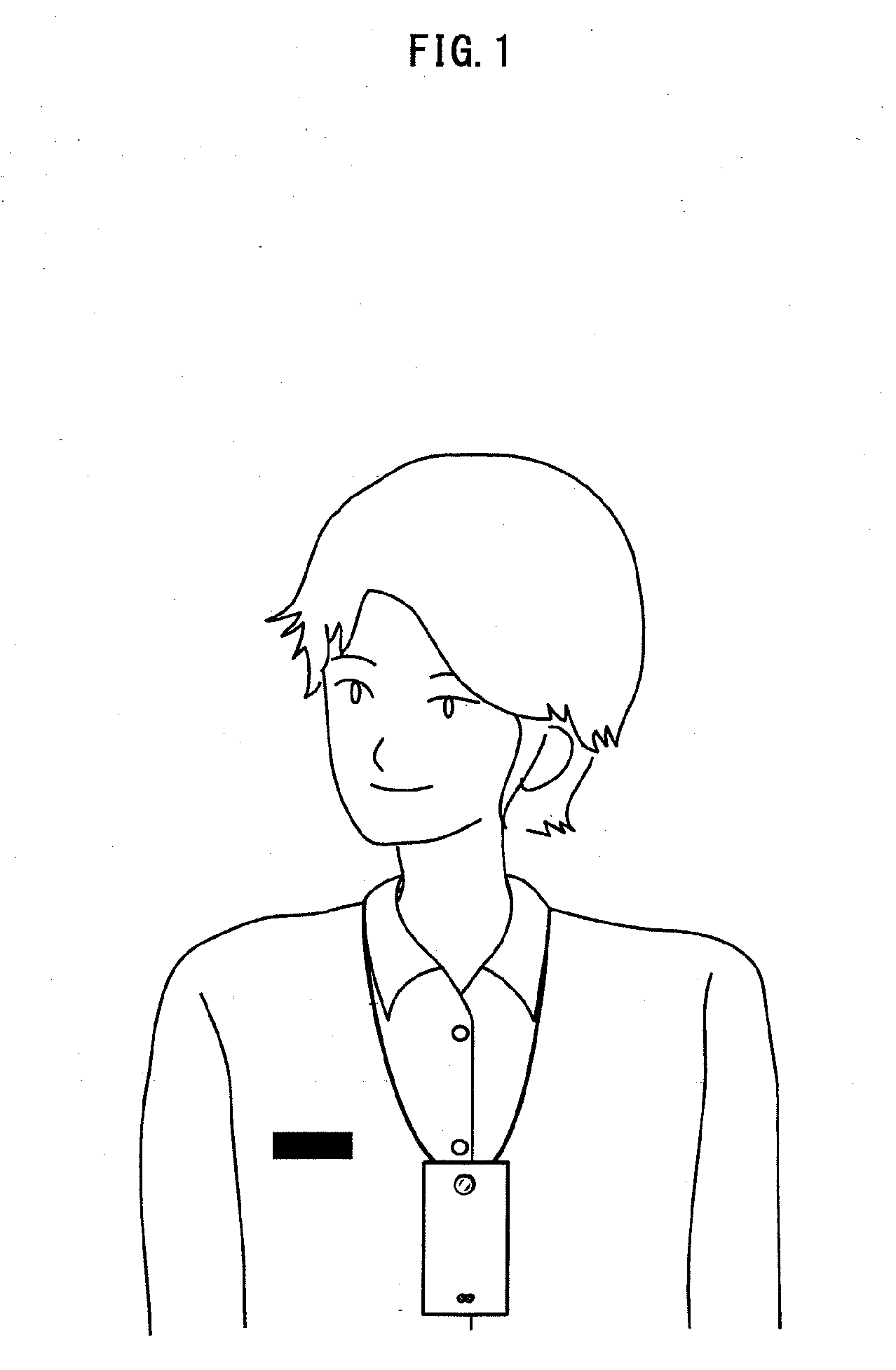
[0088]The present embodiment describes a case where the image processing device that is an example of the present invention is included in a wearable terminal, and corrects a tilt of the image captured by a camera.

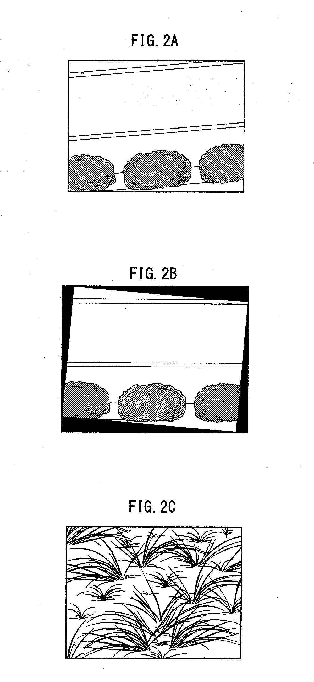
[0089]The wearable terminal is a terminal worn by the user (e.g. by dangling it around the neck) at all times, as shown in FIG. 1. The wearable terminal includes a camera, for example, for recording the daily life of the user. Images are captured by the camera without especially needing the operation by the user. Accordingly, images are likely to be captured at timing that is not expected by the user. When an image is captured with the camera tilted off the horizontal, for example, the captured image tilts as shown in FIG. 2A. Since such a tilted image does not look good, the user usually tries to correct the direction in which the object is oriented by tilting the captured image as shown in FIG. 2B. The present invention is an image processing device that estimates a righ...


PUM


Abstract

When an image is captured by an imaging apparatus such as a wearable terminal that is not on the premise that the image is captured in an upright state, it is not possible to estimate objects included in the captured image is like in order to correct a tilt of the captured image. Therefore, in some cases, a tilt angle of the captured image is possibly estimated based on one or more areas which are not suitable for estimating the tilt angle of the captured image, and the captured image is corrected based on the tilt angle incorrectly estimated. This deteriorates the quality of the captured image even worse.An image processing device pertaining to the present invention divides the captured image into a plurality of areas, determines a directional characteristic shown by a texture of each of the divided areas, and estimates the tilt angle of the captured image based on one or more areas whose textures have the unidirectional characteristic so as to correct the captured image with use of the estimated tilt angle.

Description

TECHNICAL FIELD[0001]The present invention relates to a technique for correcting an image captured by a wearable terminal.BACKGROUND ART[0002]In recent years, a wearable terminal that is capable of continuously keeping a record of daily life as a life-log has been introduced. The wearable terminal is a terminal device that can be used while being worn by a user at all times. The wearable terminal has a camera and a microphone, and is capable of keeping the record at all times without an operation by the user.[0003]A patent document 1 discloses a wearable terminal that supports the memory and memory recall of the user by defining importance levels of information pieces acquired from the camera and the microphone for each event, and capturing these information pieces according to the importance levels. However, it is problematic that, due to a usage act that the wearable terminal keeps on capturing images while being worn by the user at all times, the qualities of the captured images ...

Claims


Application Information

Patent Timeline
IPC IPC(8): G06K9/32
CPCG06T5/006G06T7/004H04N5/2628G06T2207/20021H04N5/232G06T7/401G06T7/70G06T7/41H04N23/60G06T5/80
Inventor KIMURA, MASAYUKI
Owner PANASONIC INTELLECTUAL PROPERTY CORP OF AMERICA
Learn More