

Cutting insert
a cutting insert and insert technology, applied in the field of cutting inserts, can solve the problems of shortened life of the cutting insert, heat-induced adhesion of the chip to the cutting insert, etc., and achieve the effect of reducing the height, reducing the friction of the chips, and improving the efficiency of radiating heat from the cutting
- Summary
- Abstract
- Description
- Claims
- Application Information
AI Technical Summary
Benefits of technology
Problems solved by technology
Method used
Image

Examples
Embodiment Construction
[0007]The present invention has been made to overcome the problems of the prior art discussed above, and therefore, it is an object of the present invention to provide a cutting insert with minimized friction with a chip and maximized heat-radiating performance.
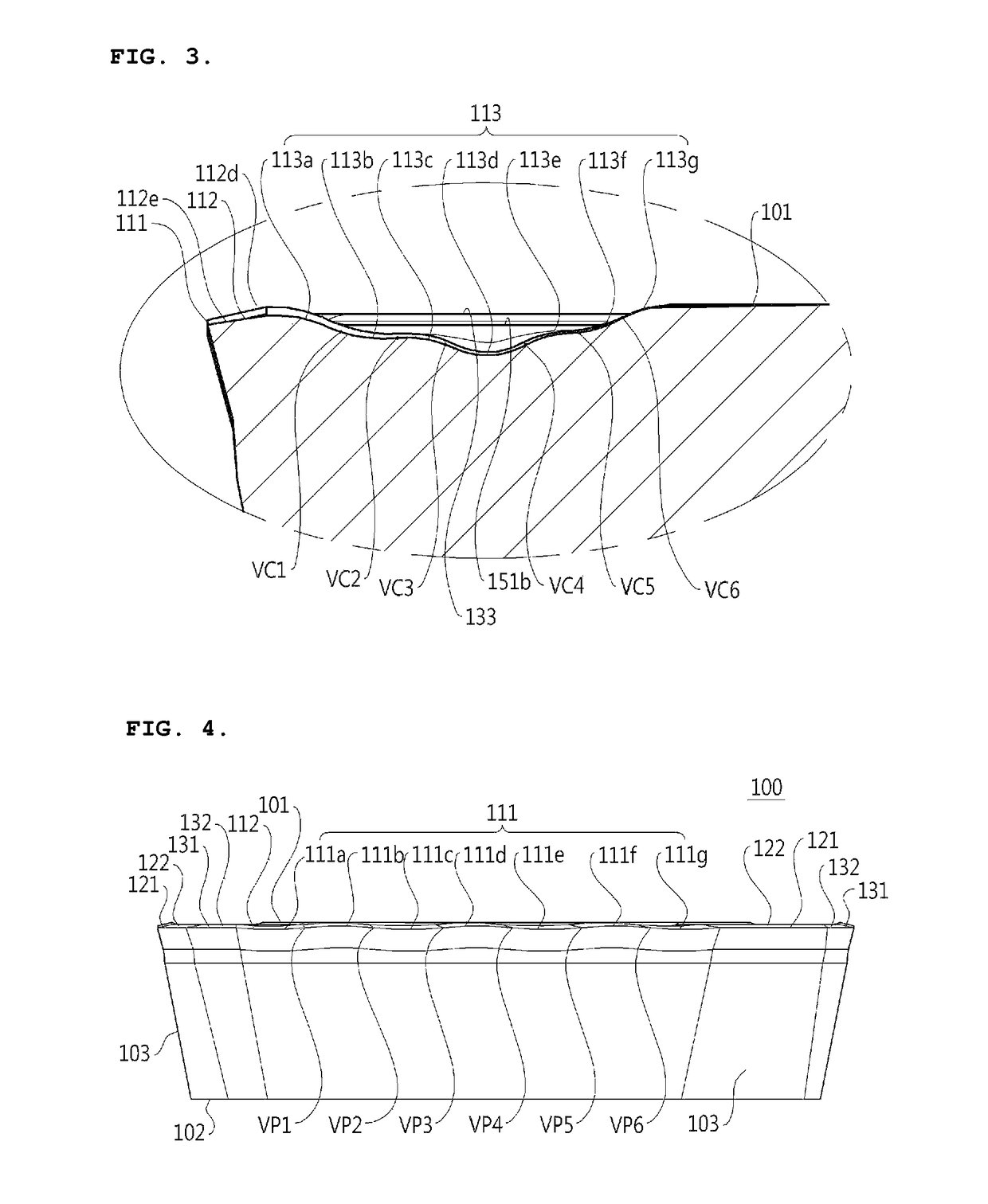
[0008]It is another object of the present invention to provide a cutting insert with improved edge strength and cutting performance by way of optimizing profile of major cutting edge and major cutting edge land surface.
[0009]It is yet another object of the present invention to provide a cutting insert from which a chip is easily releasable without being adhered.
Means to Solve the Object
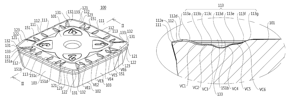
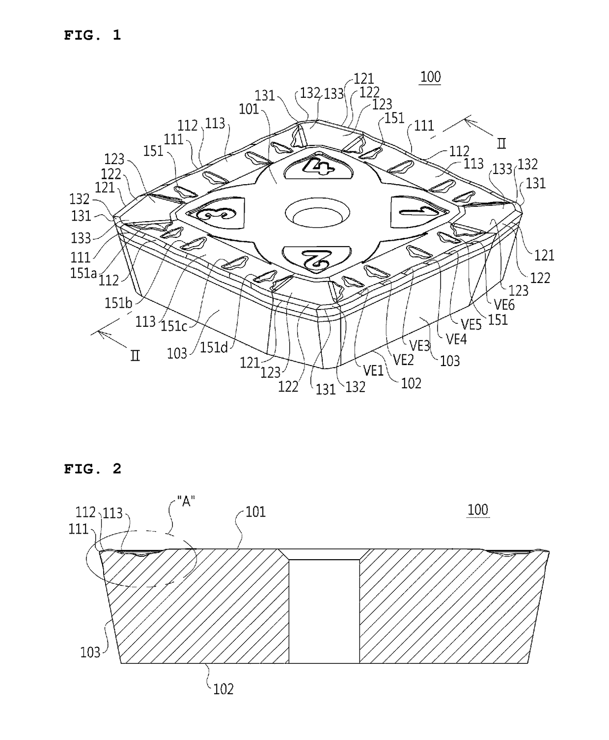
[0010]In order to accomplish the above-mentioned objects, the present invention provides a cutting insert which may include an upper surface, a lower surface, a plurality of lateral surfaces connecting the upper surface to the lower surface, a major cutting edge provided between the later surface and the upper surface, and a maj...
PUM
| Property | Measurement | Unit |
|---|---|---|
| height | aaaaa | aaaaa |
| angle | aaaaa | aaaaa |
| adhesion | aaaaa | aaaaa |
Abstract
Description
Claims
Application Information