Method for low frequency noise cancellation in magneto-resistive mixed sensors

a technology of magneto-resistive mixed sensor and low frequency cancellation, which is applied in the direction of magnetic field-controlled resistor, liquid/fluent solid measurement, electric pulse generator, etc., can solve the problems of low frequency noise of mixed sensor, and resistance fluctuations

Active Publication Date: 2010-07-08
COMMISSARIAT A LENERGIE ATOMIQUE ET AUX ENERGIES ALTERNATIVES
View PDF18 Cites 9 Cited by
  • Summary
  • Abstract
  • Description
  • Claims
  • Application Information

AI Technical Summary

Benefits of technology

[0019]More specifically the present invention aims at suppressing the 1 / f noise of the mixed sensor without requiring any field source modulation.

Problems solved by technology

The low frequency noise of a mixed sensor is due to the low frequency resistance noise of the magneto-resistive element.
However, this technique is not suppressing the low frequency noise of the magneto-resistive element.
This technique can be used to work at a frequency higher than the low frequency noise but if it suppresses the low frequency noise coming from the preamplification chain, it does not suppress the noise coming from the resistance fluctuations.
These approaches cannot be applied to mixed sensors due to their linear response in the working field range.
This technique has also been tested on mixed sensors (Document WO 2004 / 068152 A1) but its efficiency, which is proportional to the second derivative of the resistance variation, is not sufficiently competitive due to the low non linearity of the magneto-resistive sensors.
However, that technique cannot be applied when the field source cannot be modulated.
743-746 However, that technique is very specific to Hall sensors due to the vectorial nature of the Hall resistance (the measured voltage is perpendicular to the applied current direction) and cannot be applied to magneto-resistive sensors because the measured voltage is along the applied current direction.

Method used


Image

  • Method for low frequency noise cancellation in magneto-resistive mixed sensors
  • Method for low frequency noise cancellation in magneto-resistive mixed sensors
  • Method for low frequency noise cancellation in magneto-resistive mixed sensors

Examples


Embodiment Construction

[0046]The invention essentially addresses a method which cancels the 1 / f noise of magneto-resistive elements in mixed sensors.

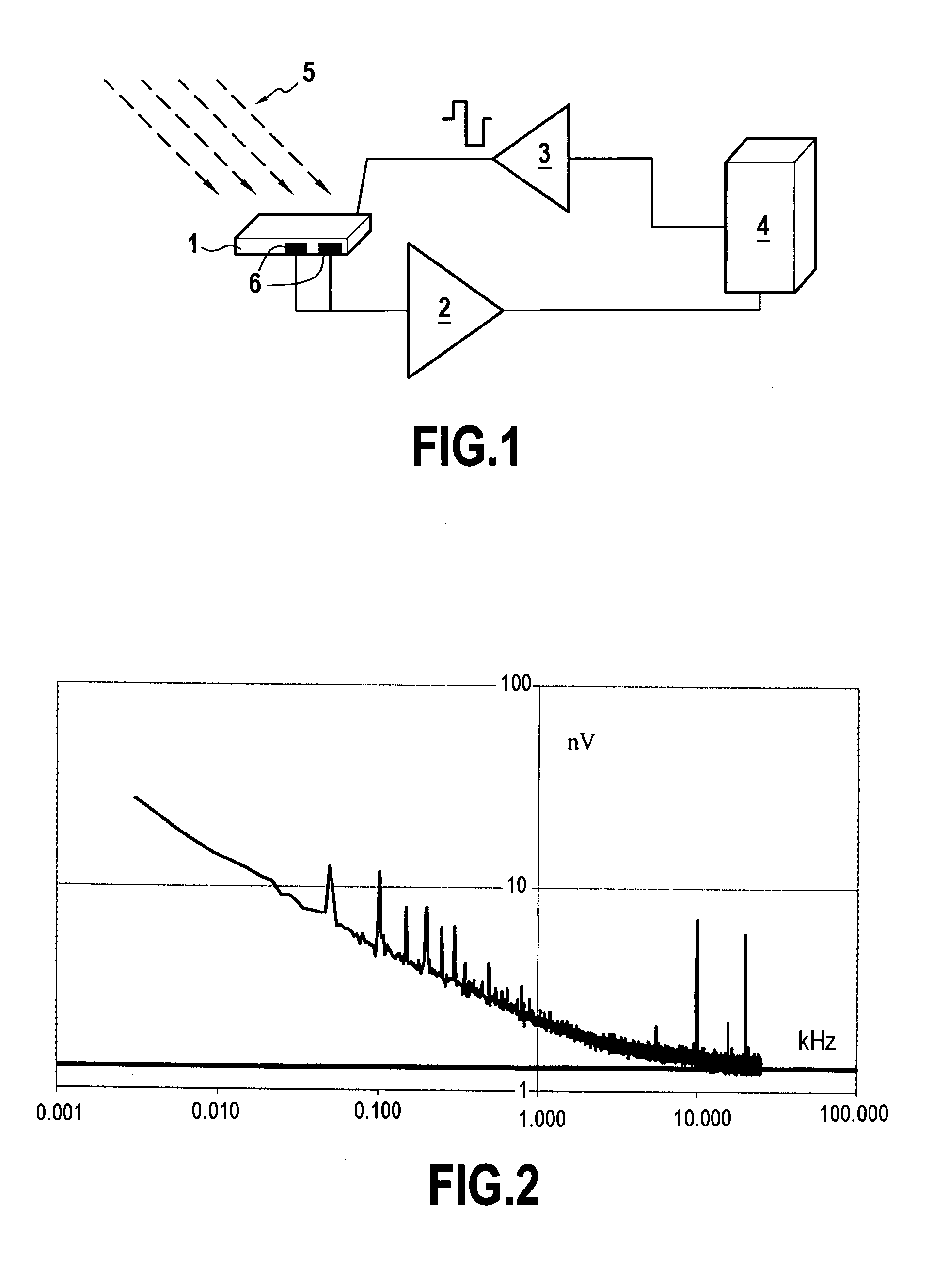
[0047]The principle of the measurement method will be explained hereafter with reference to FIG. 1.

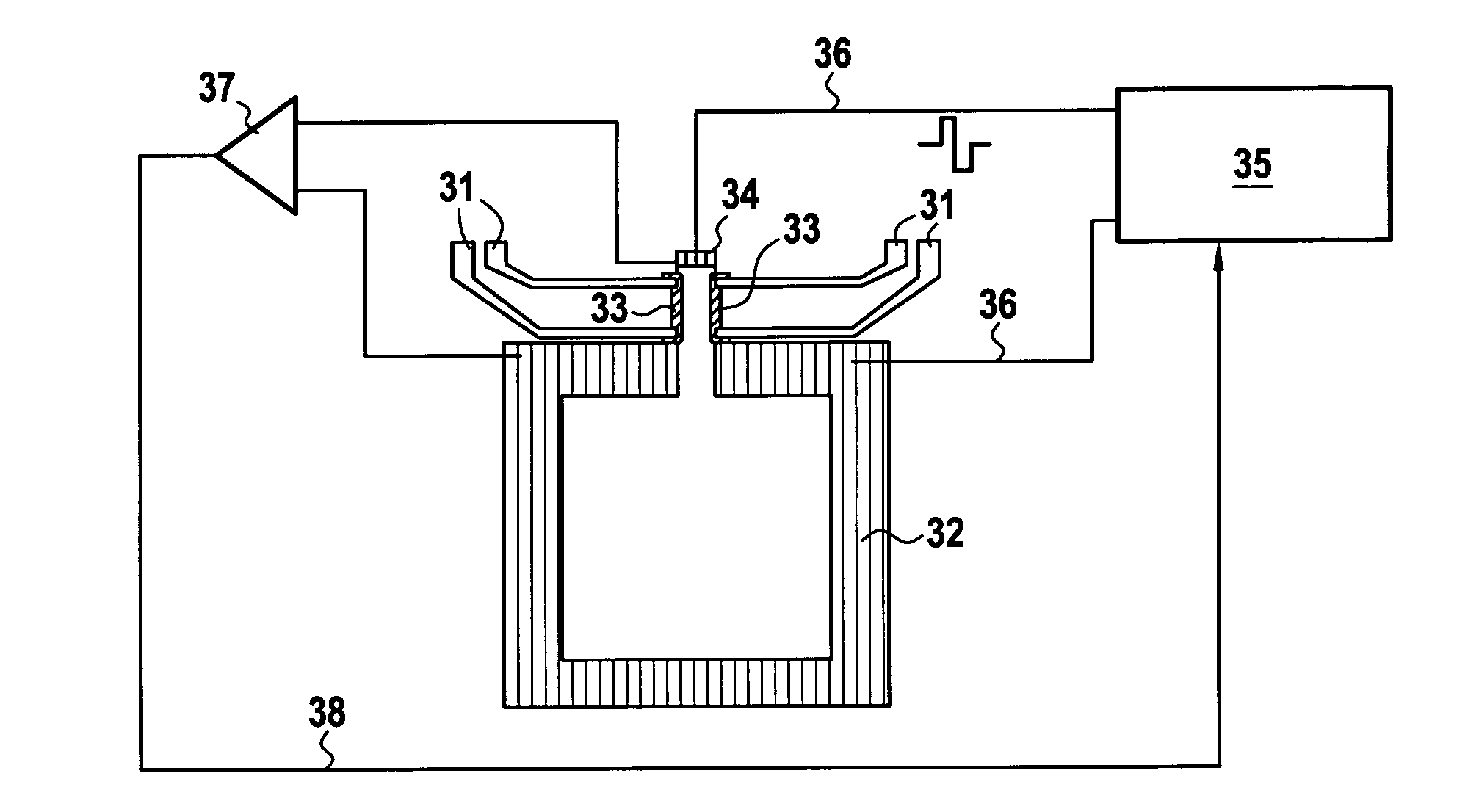
[0048]The mixed sensor 1 is submitted to an external field 5. The mixed sensor 1 contains several magneto-resistive elements 6 which can present low frequency noise which appears as resistance fluctuations. An external action controlled by a computing system 4 is applied through an interface 3 to the mixed sensor 1. The outputs of the magneto-resistive elements 6 are amplified in an amplifier 2 and transmitted to the computing system 4 which performs the necessary subtractions.

[0049]FIG. 2 shows a typical voltage noise of a magnetoresistive element. A 1 / f noise appears below a frequency fc which depends on the material properties and magnetoresistive element configuration. In this example, fc is 10 KHz. The horizontal line is the thermal noise due to the resista...


PUM


Abstract

The method for cancellation of low frequency noise in a magneto-resistive mixed sensor (1) comprising at least a superconducting loop with at least one constriction and at least one magneto-resistive element (6) comprises a set of measuring steps with at least one measuring step being conducted with the normal running of the mixed sensor and at least another measuring step being conducted whilst an additional super-current is temporarily injected in the at least one constriction of the at least one superconducting loop of the mixed sensor (1) up to a critical super-current of the constriction so that the result of the at least another measuring step is used as a reference level of the at least one magneto-resistive element (6).

Description

BACKGROUND OF THE INVENTION[0001]1. Field of the Invention[0002]The present invention relates to a method for low frequency cancellation of noise in magneto-resistive mixed sensors.[0003]The invention more specifically relates to a method for cancellation of low frequency noise in a magneto-resistive mixed sensor comprising at least a superconducting loop with at least one constriction and at least one magneto-resistive element.[0004]Low frequency noise refers to the resistance noise of the magneto-resistive element created by low frequency fluctuations. This kind of noise appears in all physical systems and increases as the size of the system decreases. If f is the frequency of the low frequency fluctuations, the power density of the noise decreases as 1 / fα where α is of the order of 1.[0005]2. Description of the Related Art[0006]The principle of mixed sensors which associate at least one superconducting loop and one magneto-resistive element for low frequency and RF applications i...

Claims


Application Information

Patent Timeline
Patent Type & Authority Applications(United States)
IPC IPC(8): H01L39/00G01R15/20G01R33/035G01D5/14H01L43/08
CPCB82Y25/00G01R33/035G01R33/093G01R33/0358G01R33/0354
Inventor FERMON, CLAUDEPOLOVY, HEDWIGEPANNETIER-LECOEUR, MYRIAM
Owner COMMISSARIAT A LENERGIE ATOMIQUE ET AUX ENERGIES ALTERNATIVES
Why Eureka
Try Eureka