Ostomy Appliance
- Summary
- Abstract
- Description
- Claims
- Application Information
AI Technical Summary
Benefits of technology
Problems solved by technology
Method used
Image

Examples
second embodiment
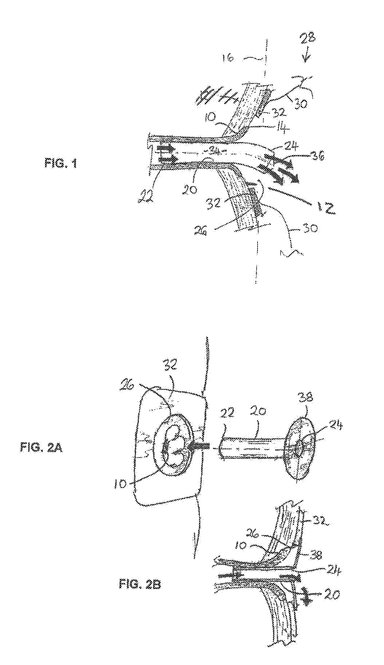
[0084]FIGS. 2a and 2B illustrate a second embodiment in which the distal end 24 of the stoma adapter 20 comprises a shoulder or flange 38. The flange 38 acts as a stop to limit the degree of insertion of the stoma adapter 20 into the stoma 10. In the present embodiment, the flange 38 additionally is dimensioned to engage the body fitment 32. For example, the flange 38 is slightly larger in diameter than the entrance aperture 26 in the adhesive body fitment 32. The flange 38 is configured to engage the rear surface (in FIG. 2B) or alternatively the front surface (not shown) of the body fitment 38. For a one-piece appliance, the stoma adapter 20 can be inserted at the stoma 10 before the body fitment 32 of the ostomy appliance 28 is attached to the peristomal skin 12, such that the periphery of the flange 38 is trapped between the skin 12 and the body fitment 32 to hold the stoma adapter 20 positively in position.
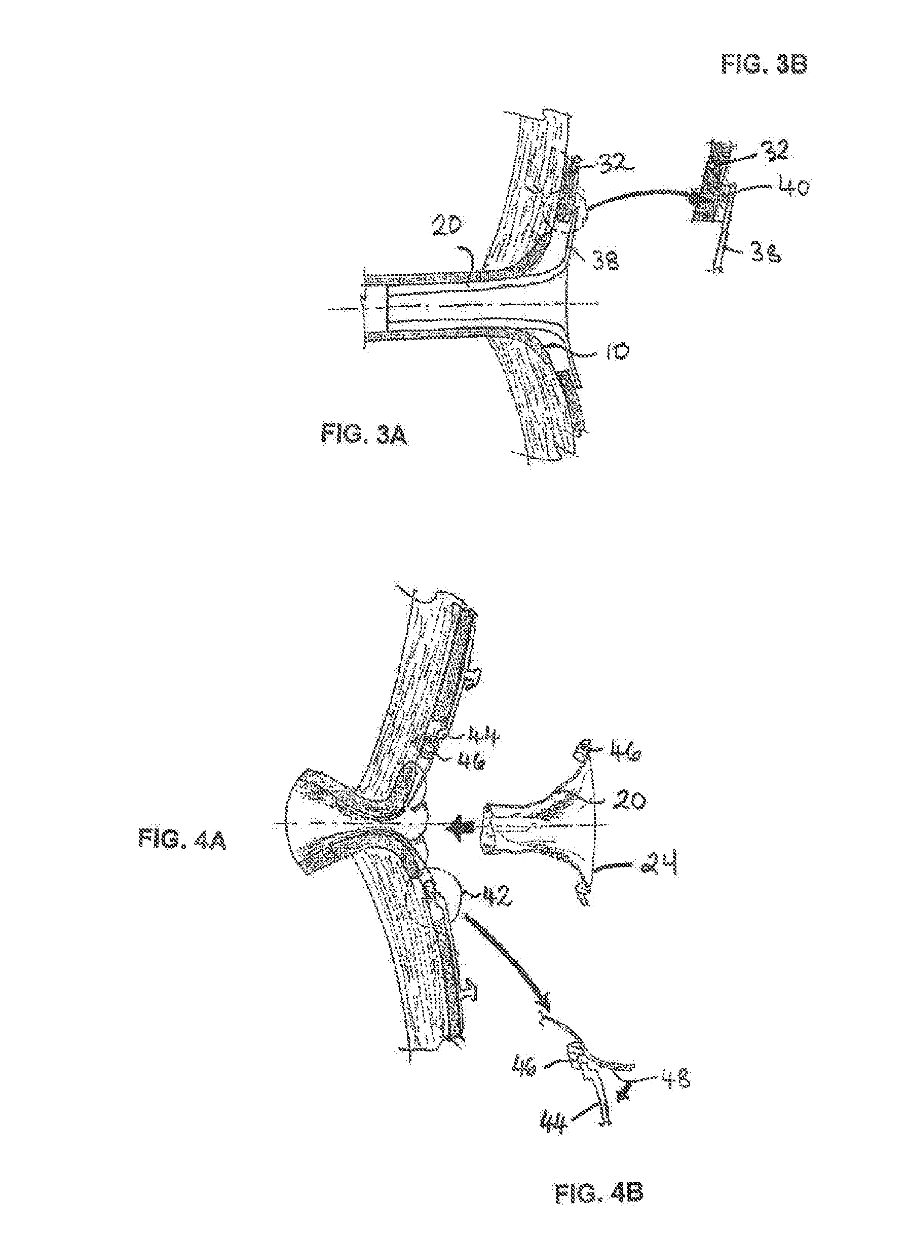
[0085]FIGS. 3A and 3B shows a modified third embodiment similar to the s...
fourth embodiment
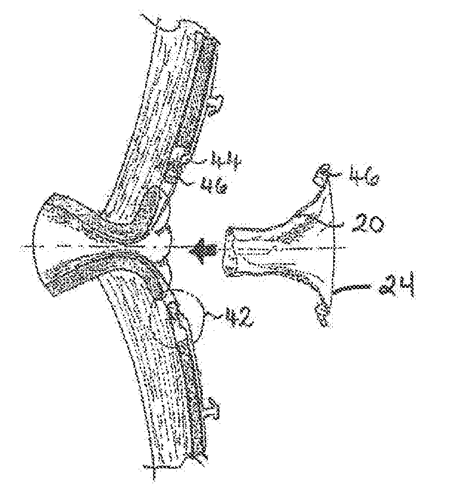
[0089]Also, in the fourth embodiment, the stoma adapter 20 generally has a more conic shape, at least towards the distal end 24, so that the flange is less pronounced.
[0090]As seen in FIGS. 4B and 4C, the distal end 24 of the stoma adapter 20 may extend out past the stoma 10 and then return to attach to the body fitment 32. Such a shape would allow the stoma adapter 20 to move axially with the stoma 10 without placing unwanted stress on the attachment to the body fitment 32.
[0091]Formation of the stoma adapter 20 can be accomplished by a variety of methods. These include, but are not limited to, injection molding, blow molding and longitudinal seal bonding of flat sheet material to form a tube. The tube material may or may not, as desired, have gas barrier properties to contain or manage odor. The stoma adapter 20 material may or may not, as desired, have properties that reduce the friction of effluent flow along its length, in order to promote easier discharge of effluent. The stom...
PUM
 Abstract
Description
Claims
Application Information
 - Generate Ideas
- Intellectual Property
- Life Sciences
- Materials
- Tech Scout
- Unparalleled Data Quality
- Higher Quality Content
- 60% Fewer Hallucinations
Browse by: Latest US Patents, China's latest patents, Technical Efficacy Thesaurus, Application Domain, Technology Topic, Popular Technical Reports.
© 2025 PatSnap. All rights reserved.Legal|Privacy policy|Modern Slavery Act Transparency Statement|Sitemap|About US| Contact US: help@patsnap.com