Device for catheter sheath retraction

a technology of catheter sheath and device, which is applied in the field of catheter sheath retraction devices, can solve the problems of catheter compression producing undesirable, catheter withdrawal not being specifically accounted for the inherent residual tolerance and material resilience of surgical catheter construction, and preventing premature catheter withdrawal or unnecessary further movement of the elongate member. , the effect of being readily adaptable to different situations

Active Publication Date: 2010-07-08
CR BARD INC
View PDF100 Cites 112 Cited by
  • Summary
  • Abstract
  • Description
  • Claims
  • Application Information

AI Technical Summary

Benefits of technology

[0051]Embodiments of the second, third, fifth and sixth aspects of the invention set forth above can indicate to the user of the device, when a stent at the elongate body distal end has been fully released, preventing premature catheter withdrawal or unnecessary further movement of the elongate member, and are readily adaptable to different lengths of stent which the devices may be employed to release.

Problems solved by technology

The overall effect of the tolerances provided to allow such flexibility and relative motion means that when the operator comes to retract the sheath, the initial stages of sheath retraction may not deliver a controlled or expected degree of motion in the sheath, as the slack is taken up.
This initial catheter compression can produce undesirable preliminary motion at the catheter distal end as the sheath retraction device is first actuated.
Whilst prior art devices including two or more separate retraction mechanisms for delivering different mechanical advantages have been provided, so as to achieve slow initial sheath withdrawal for accurate placement of the stent distal end and fast subsequent sheath withdrawal for quickly releasing the stent when placed, no device has yet been produced to specifically account for the inherent residual tolerances and material resilience of the surgical catheter construction.

Method used


Image

  • Device for catheter sheath retraction
  • Device for catheter sheath retraction
  • Device for catheter sheath retraction

Examples


Embodiment Construction

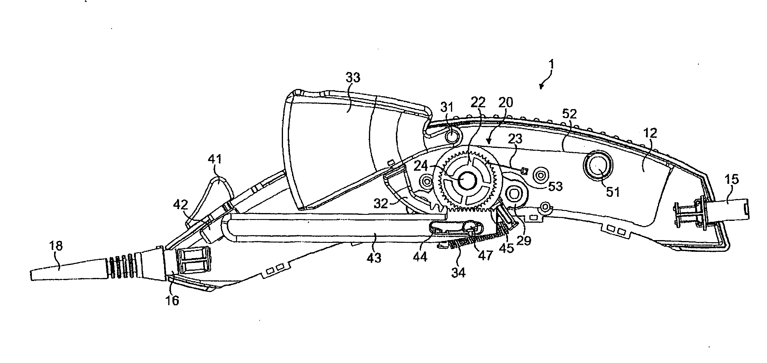
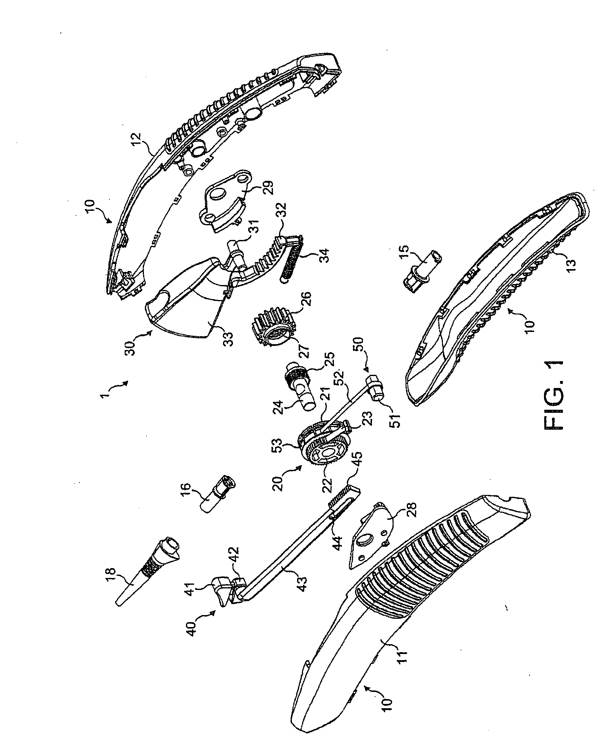
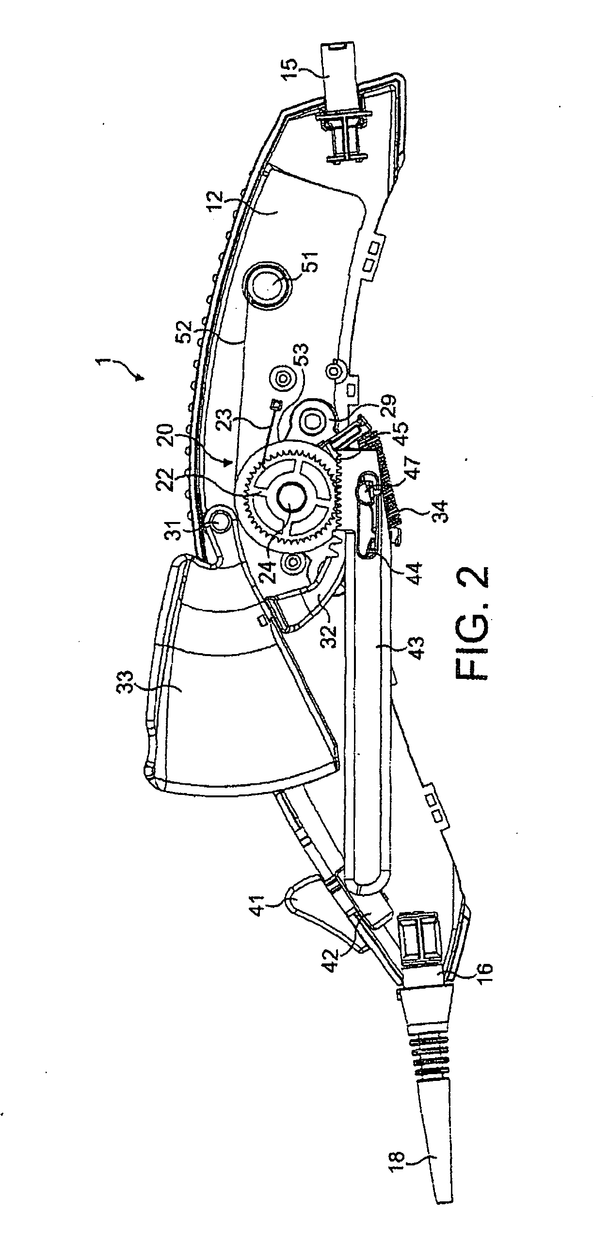
[0063]The following detailed description is directed to a specific example of a catheter sheath retraction device, suitable for connection to the proximal end of a stent delivery catheter (elongate body) for retracting the catheter outer sheath, by virtue of a sheath retraction wire (elongate member), so as to expose a stent at the distal end of the catheter. It will be appreciated, however, that the utility of the disclosed device and the components of the actuator mechanism may find utility in alternative applications where actuation to achieve relative motion between two elongate components is required.

[0064]In the present specification, as is usual in this technical field, the term “proximal” refers to the direction or end of the device which, when in use, is generally towards the medical practitioner, and the term “distal” refers to the opposite sense, i.e. towards the patient or away from the medical practitioner.

[0065]The following description is made with reference to FIGS. ...


PUM


Abstract

There is disclosed herein a device (1) for moving an elongate member relative to an. elongate body through which it extends, the device comprising: a housing (10) connectable to the elongate body; a mover (20) associated with the housing and connectable to the elongate member for moving the elongate member relative to the housing and relative to a connected elongate body; and a pre-mover (40) for adjusting an elongate member connected to the mover relative to an elongate body connected to the housing in preparation for moving the elongate member with the mover. There is also disclosed a related surgical apparatus.

Description

FIELD OF THE INVENTION[0001]The present invention relates to a device for moving an elongate member relative to an elongate body through which it at least partially extends, to a device for moving an elongate member by a predetermined distance relative to an elongate body through which it at least partially extends, thereby to release a stent at the distal end of the elongate body, and to surgical apparatus including such devices. More specifically, the invention is concerned with medical transluminal catheters such as those used to deliver a stent to a vascular treatment location, and the devices by which a medical practitioner operates such catheters from a location external of the patient.BACKGROUND OF THE INVENTION[0002]It has long been desirable to reduce the degree of trauma caused by, and attendant risks associated with, surgical procedures. In order to further this aim, there have been a large number of technical advances in recent times to enable various surgical procedures...

Claims


Application Information

Patent Timeline
Patent Type & Authority Applications(United States)
IPC IPC(8): A61B17/00A61F2/95A61F2/966
CPCA61F2/966A61F2002/9517A61M25/0136A61F2/95A61F2/9517
Inventor WUEBBELING, MARTINVOGEL, MICHAELDORN, JURGEN
Owner CR BARD INC
Why Eureka
Try Eureka