Degradation detection system for a hose assembly

a detection system and hose technology, applied in the field of system for detecting degradation of hose assemblies, can solve the problems of increased strength of hose design, increased cost of hose fatigue resistance, and burst tes

Active Publication Date: 2010-07-08
DANFOSS POWER SOLUTIONS II TECH AS
View PDF10 Cites 109 Cited by
  • Summary
  • Abstract
  • Description
  • Claims
  • Application Information

AI Technical Summary

Problems solved by technology

Using conventional technology, the burst strength of a hose design may be increased by adding additional reinforcing material and/or layers, a practice which is generally discouraged because of its negative impact on the flexibility of the hose, or by universally increasing the te...

Method used


Image

  • Degradation detection system for a hose assembly
  • Degradation detection system for a hose assembly
  • Degradation detection system for a hose assembly

Examples


Embodiment Construction

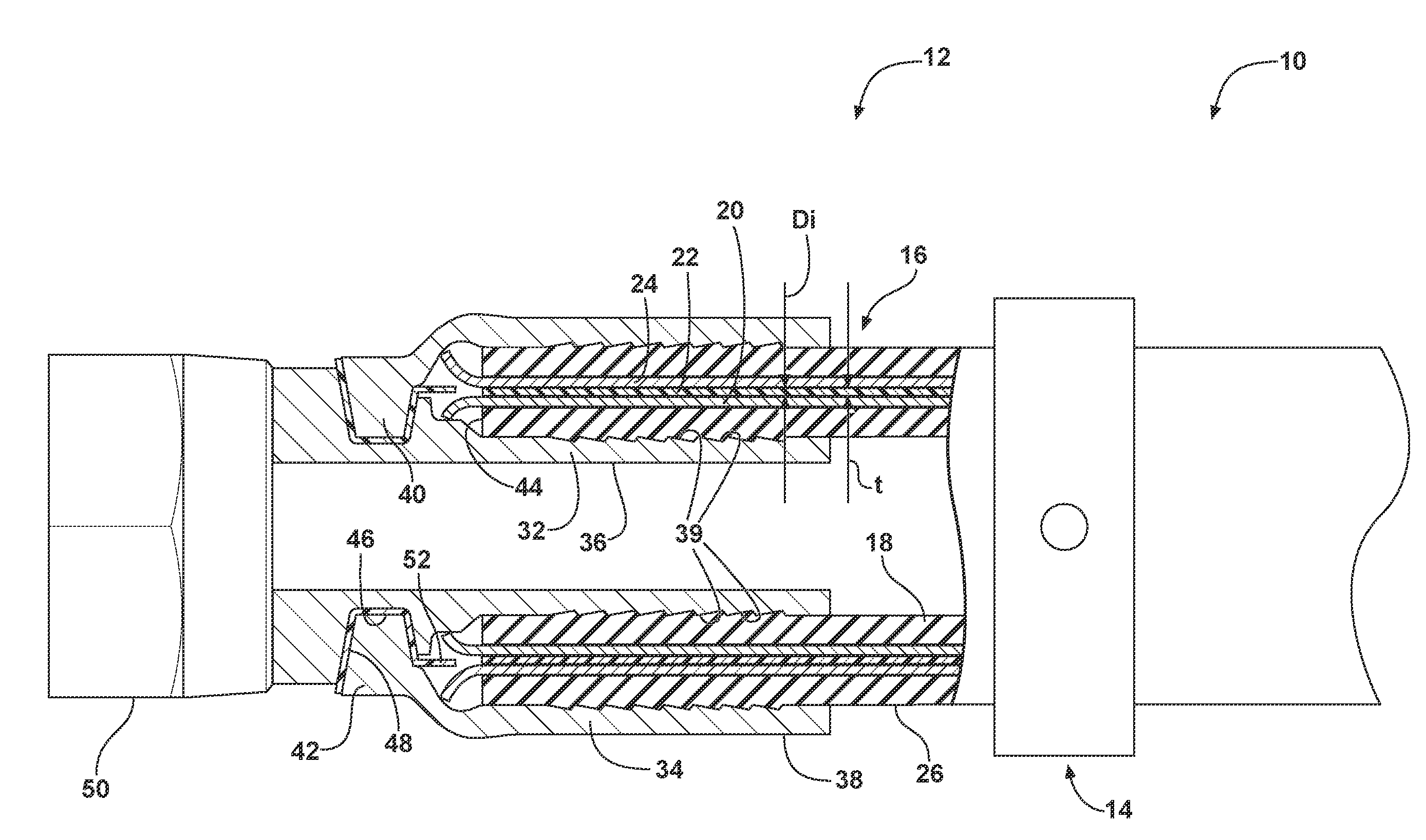
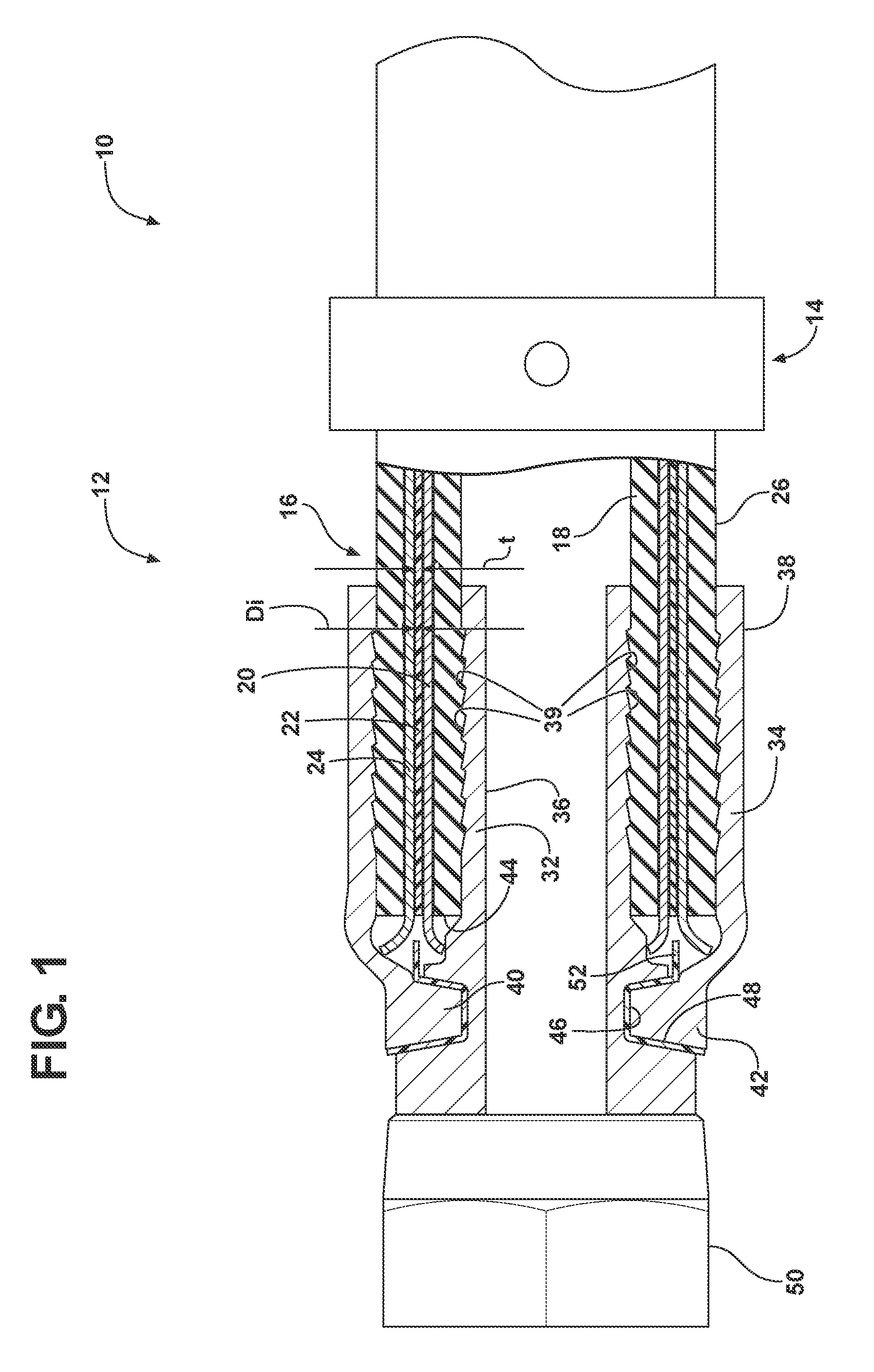
[0033]Referring to the drawings, wherein like reference numbers refer to like components, FIG. 1 shows a hose fault detection system, generally designated at 10. The hose fault detection system 10 includes a hose assembly, generally designated 12, and a fault detector 14 in electrical communication with the hose assembly 12.

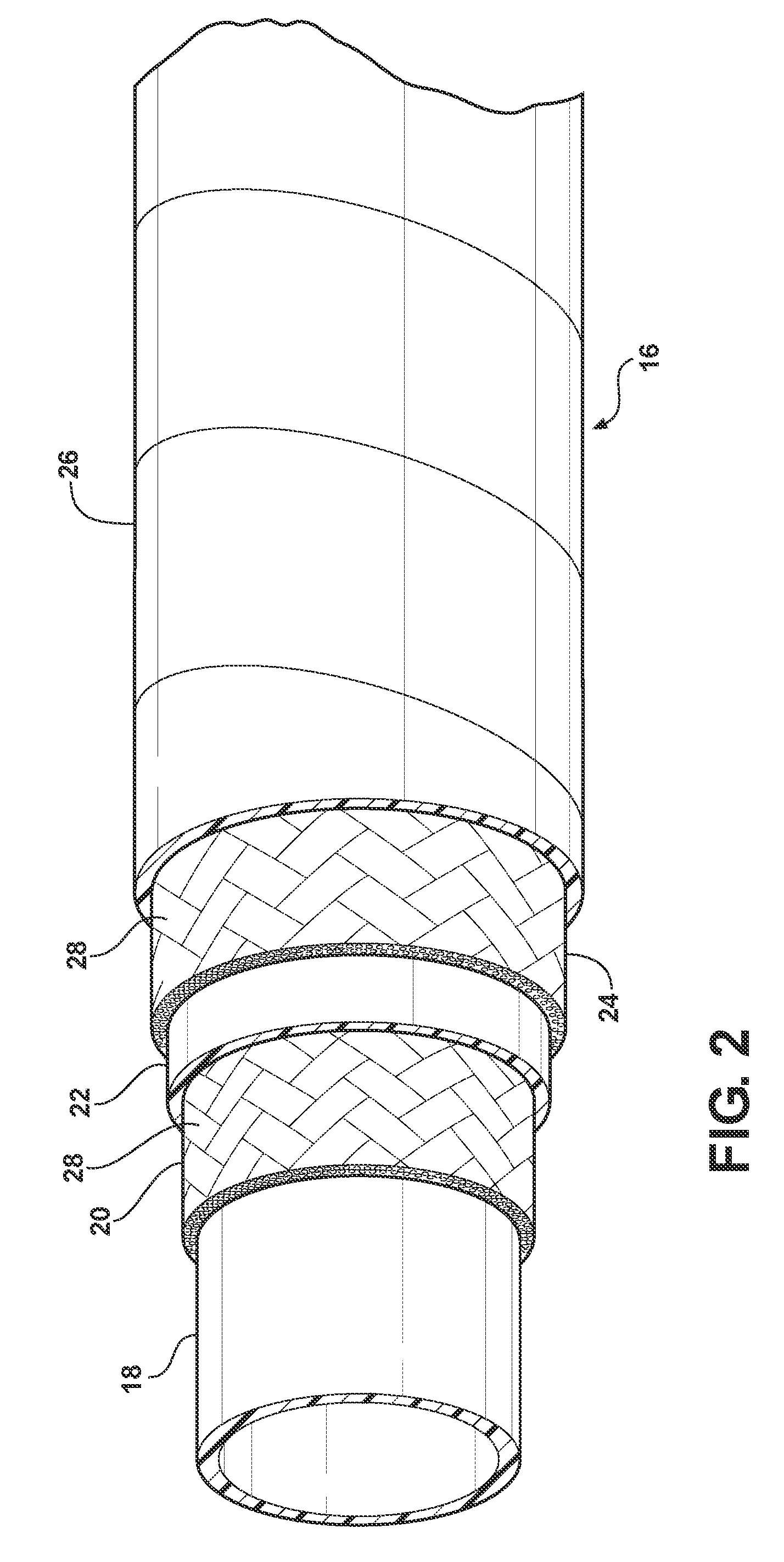
[0034]The hose assembly 12 includes a hose, generally designated 16, having a multi-layer construction. In the subject embodiment, the hose 16 is generally flexible and includes an inner tube 18 made from a polymeric material, such as rubber or plastic, or another material depending on the requirements of the particular application, a first conductive layer 20, an intermediate layer 22, a second conductive layer 24 and an outer cover 26. The first and second conductive layers 20, 24 and the intermediate layer 22 define an electrical characteristic of the hose assembly 12, such as capacitance, inductance and / or resistance (impedance).

[0035]In the subject embodimen...


PUM


Abstract

A hose fault detection system includes a hose assembly including a hose having first and second conductive layers. The hose assembly has an electrical characteristic. A fault detector is in electrical communication with the first and second conductive layers. The fault detector includes an indicator operatively connected to the hose assembly. A method for monitoring the structural integrity of a hose assembly includes providing a fault detection system having a hose assembly including a hose having a first conductive layer and a second conductive layer. The hose assembly has an electrical characteristic. The electrical characteristic of the hose assembly is compared to a threshold value. A visual indicator in operative communication with the hose assembly is illuminated when the electrical characteristic goes beyond the threshold value.

Description

CROSS-REFERENCE TO RELATED APPLICATIONS[0001]This application claims the benefit of U.S. Provisional Application 61 / 142,752, filed Jan. 6, 2009, and which is hereby incorporated by reference in its entirety.TECHNICAL FIELD[0002]The present invention relates to a system for detecting degradation of a hose assembly.BACKGROUND OF THE INVENTION[0003]High pressure reinforced hydraulic hose is typically used on a variety of fluid power operated machines, such as earth-moving machines, to provide a flexible connection between several moving parts of a hydraulic circuit employed on or within the machine. Such hoses may include a hollow polymeric inner tube on which successive cylindrical layers of reinforcing material, such as wire or textile, are concentrically applied to contain the radial and axial pressures developed within the inner tube.[0004]Many applications require hose constructions with both high burst strength and long term fatigue resistance. Using conventional technology, the ...

Claims


Application Information

Patent Timeline
IPC IPC(8): G06F19/00G01N27/20
CPCF16L11/127F16L25/01F16L2201/30G01M3/18G01M5/0025H04Q2209/823G01M5/0083G01N27/20H04Q9/00H04Q2209/47H04Q2209/75G01M5/0033G01M3/40G06K7/00G08C17/00
Inventor PEREIRA, LUIS R.PIER, B. THOMASBHADKAMKAR, ATUL S.GUNGOR, VEHBI C.RENTEL, CARLOS H.STARK, JASON D.SMITH, SCOTT A.
Owner DANFOSS POWER SOLUTIONS II TECH AS
Why Eureka
Try Eureka