Two piece rail system for firearm

Inactive Publication Date: 2010-07-15
HINES STEVE
View PDF43 Cites 43 Cited by
  • Summary
  • Abstract
  • Description
  • Claims
  • Application Information

AI Technical Summary

Benefits of technology

[0013]The half guards can incorporate elements to prevent the assembled handguard from rotating around the barrel nut. In some embodiments, the half guards themselves are machined, m

Problems solved by technology

As such, the handguard is not as rigidly attached as is often desired.
Tightening the

Method used


Image

  • Two piece rail system for firearm
  • Two piece rail system for firearm
  • Two piece rail system for firearm

Examples


Embodiment Construction

[0029]The particular values and configurations discussed in these non-limiting examples can be varied and are cited merely to illustrate at least one embodiment and are not intended to limit the scope thereof. In general, the figures are not to scale.

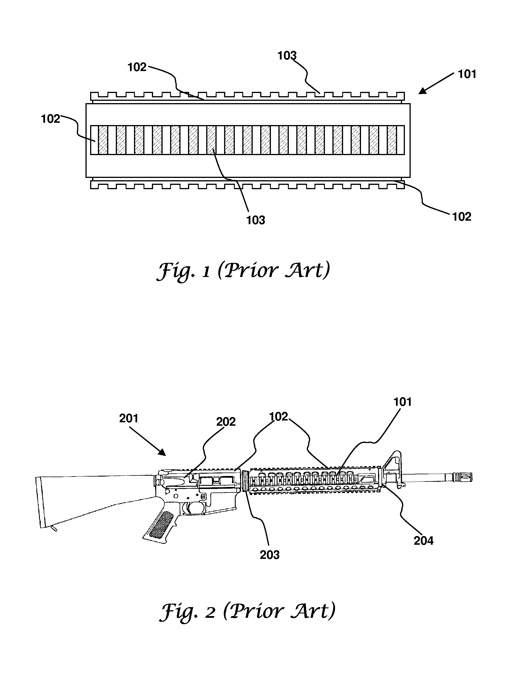
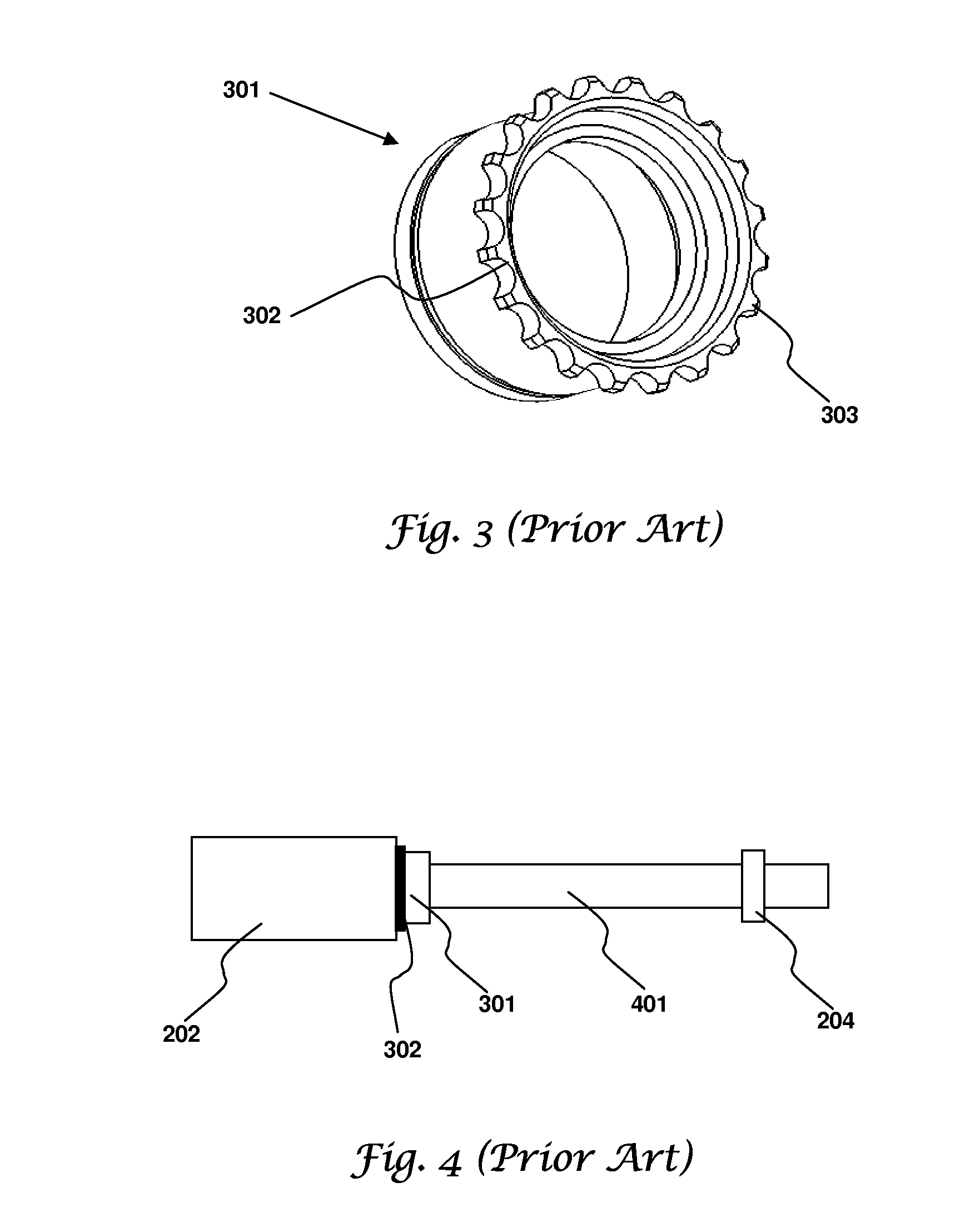
[0030]A firearm handguard having two identical halves, or half guards, can engage the barrel nut of certain firearms to thereby provide a mounting rail system. The barrel nut attaches the barrel to the receiver. The half guards can be separately positioned in engagement with the barrel nut before fastening them together. The fastening operation can cause the half guards to clamp onto the barrel nut. Alternatively, the front handguard cup of some firearms can prevent the handguard from slipping forward while the rear barrel nut engagement prevents handguard rotation. Free floating variants, however, must clamp onto the barrel nut.

[0031]FIG. 5 illustrates a quarter front view of a half guard 501 in accordance with aspects of some embodime...


PUM


Abstract

A firearm handguard having two identical halves, or half guards, can engage the barrel nut of certain firearms to thereby provide a mounting rail system. The barrel nut attaches the barrel to the receiver. The half guards can be separately positioned in engagement with the barrel nut before fastening them together. The fastening operation can cause the half guards to clamp onto the barrel nut. Alternatively, the front handguard cup of some firearms can prevent the handguard from slipping forward while the rear barrel nut engagement prevents handguard rotation. Free floating variants, however, must clamp onto the barrel nut.

Description

CROSS REFERENCE TO RELATED APPLICATIONS[0001]This patent application claims the priority and benefit of U.S. Provisional Patent Application No. 61 / 143,795 filed on Jan. 11, 2009 entitled “Firearm Vertical Fore Grip and Rail System” and which is incorporated herein by reference in its entirety.TECHNICAL FIELD[0002]Embodiments relate to the fields of small arms, rifle handguards, carbine handguards, and mounting rails.BACKGROUND[0003]Current small arms use mounting rail systems for attaching accessories to the small arm. For example, M4 and M16 carbines are often fitted with a single piece handguard that incorporates up to four Picatinny rails. Picatinny rails are well known mounting rails that meet the specifications contained in MIL-STD-1913 and MIL-STD-1913 Notice 1. Another mounting rail called the Weaver rail is a notoriously well known variation of the Picatinny rail. Battaglia discloses a mounting rail system in U.S. Pat. No. 6,792,711 while Olson discloses another in U.S. Pat....

Claims


Application Information

Patent Timeline
IPC IPC(8): F41C23/16
CPCF41C23/16
Inventor HINES, STEVE
Owner HINES STEVE
Why Eureka
Try Eureka