
Orientation sensor for downhole tool

Inactive Publication Date: 2010-07-15
ALLAN VICTOR LAING
View PDF1 Cites 28 Cited by
  • Summary
  • Abstract
  • Description
  • Claims
  • Application Information

AI Technical Summary

Benefits of technology

[0012]This provides the advantage of enabling at least one orientation sensor to be mounted to a non-rotating sleeve of the downhole tool. In the case in which the orientation sensor is an accelerometer, the accelerometer signals are then less prone to disturbance by vibration caused by the rotating shaft, as a result of which the orientation sensor can be used continuously while the shaft is rotating. By providing a signal receiving means in electromagnetic communication with the signal transmitting means, this enables a signal generated by the orientation sensor to be supplied to a measurement while drilling (MWD) tool connected to the rotating shaft, which in turn facilitates communication of the signal to the surface.
[0017]This provides the advantage that the orientation sensor does not require a separate power supply, which further provides the advantage that difficult and inconvenient replacement of the power supply is avoided.
[0023]This provides the advantage that a single component for transmitting power to the sensor and receiving signals from the sensor can be used.

Problems solved by technology

It has generally been considered necessary to mount the MWD tool and accelerometers to the rotating shaft, because of insufficient space on the non-rotating sleeve during use, and the difficulty / complexity associated with providing power between the rotating shaft and the non-rotating sleeve.
However, this provides the disadvantages that because the accelerometers are sensitive to vibration and acceleration, it is generally very difficult or even impossible to obtain signals from the accelerometer mounted to the rotating shaft while the shaft is rotating.
As a result, accelerometer signals, and therefore an indication of the orientation of the housing relative to the borehole, can generally only be obtained when the rotary shaft is stationary, or moving slowly, as a result of which orientation indication signals can only be obtained at discrete intervals, and not continuously while the drilling apparatus is in operation, because of undesirability of ceasing drilling.

Method used


Image

  • Orientation sensor for downhole tool
  • Orientation sensor for downhole tool
  • Orientation sensor for downhole tool

Examples


Embodiment Construction

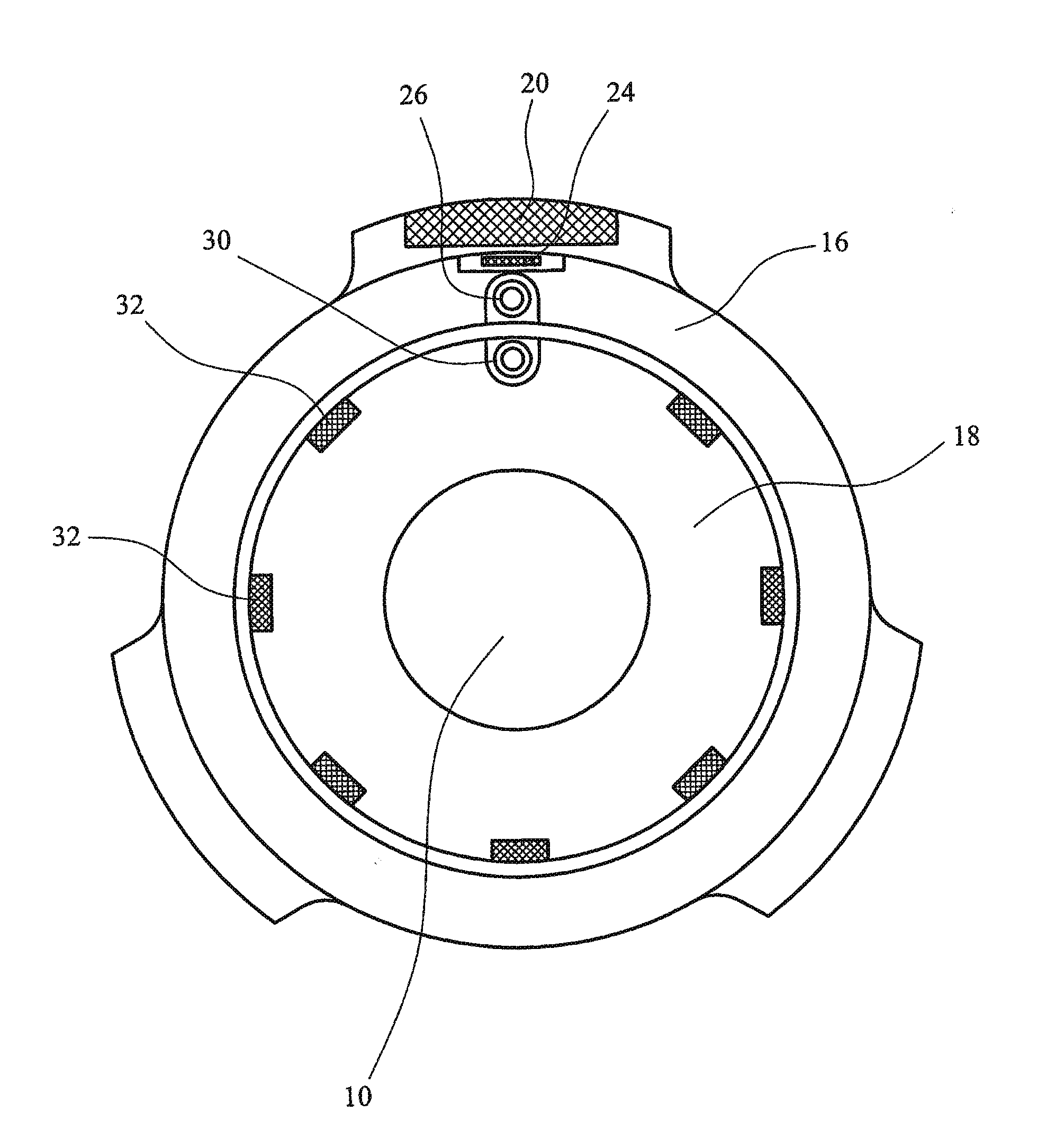
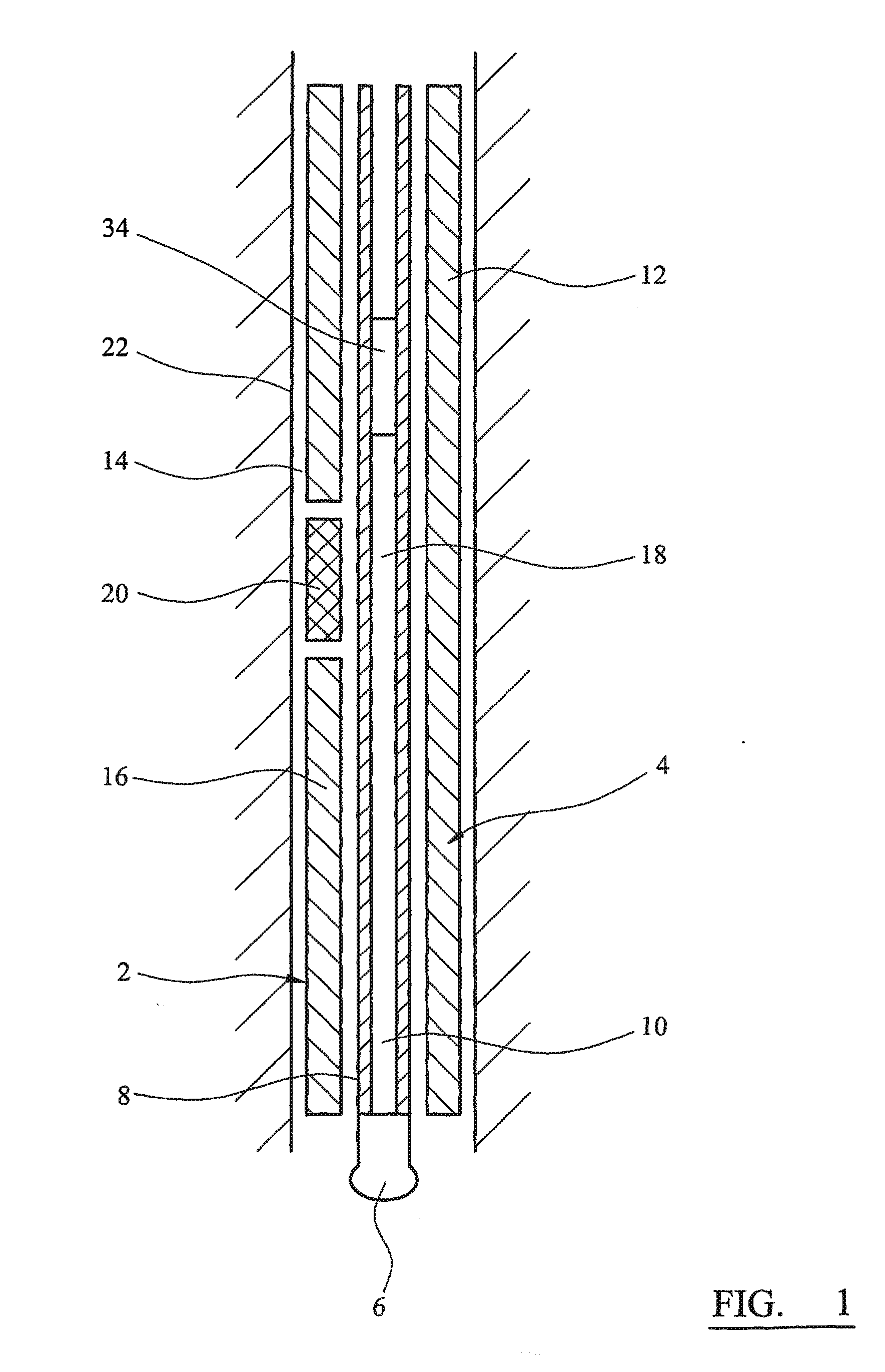
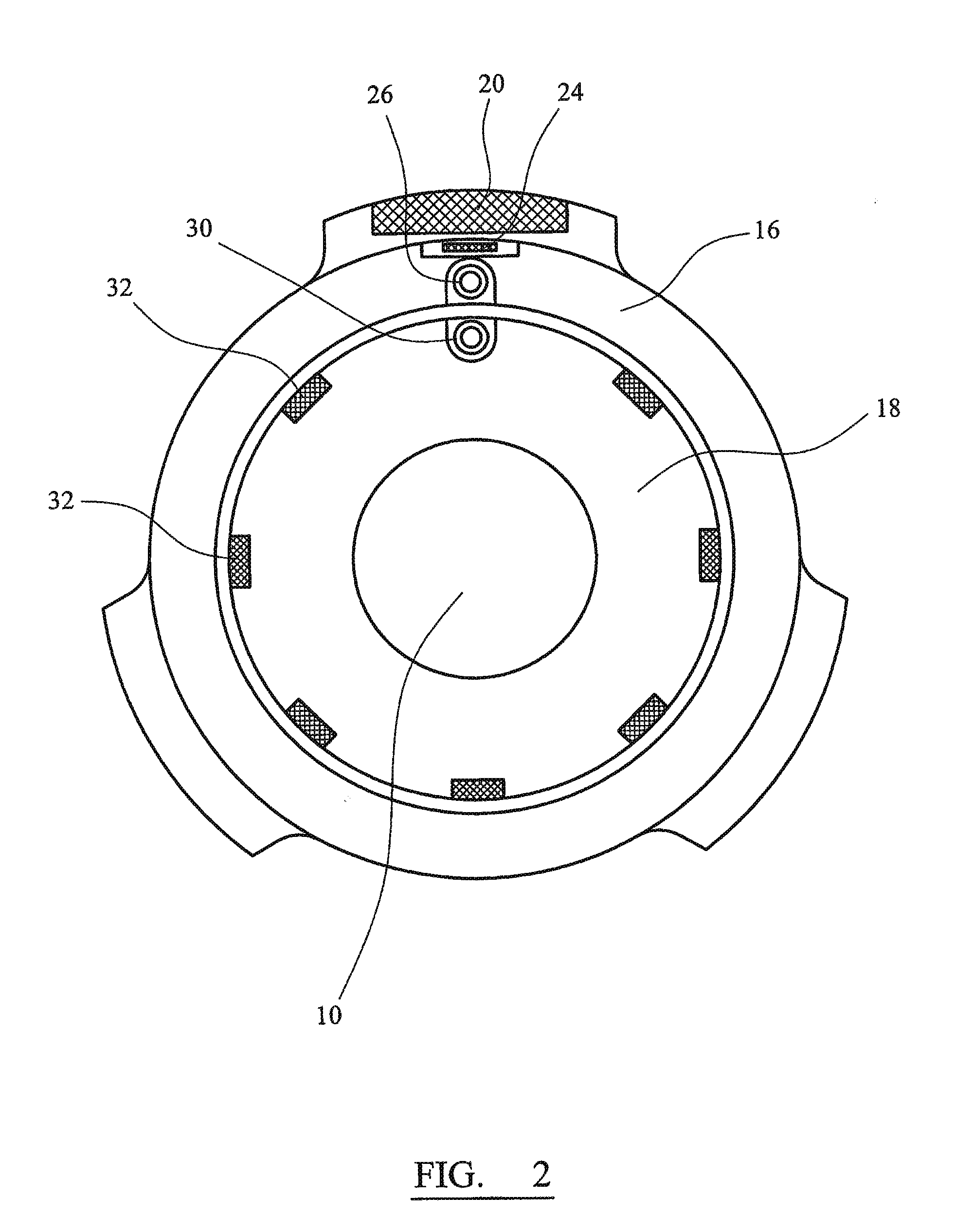
[0034]Referring to FIG. 1, a downhole drilling apparatus 2 in the form of a drill string incorporating a rotary steerable tool 4 embodying the present invention has a drill bit 6 mounted to a hollow shaft 8 defining a passage 10 for transmitting drilling fluid to the drill bit 6, and an outer housing 12 to which the shaft 8 is mounted, and which defines an annular chamber 14 for enabling drilling fluid and drilling debris to return to the surface from the drill bit 6. The outer housing 12 is connected to the shaft 8 by means of a clutch (not shown) for causing the housing 12 to rotate with the shaft 8 when the tool 4 is in its orienting mode, or straight drilling mode in order to improve the drilling efficiency of the apparatus 2, and for enabling the shaft 8 to rotate relative to the outer housing 12 when the tool 4 is in its directional drilling mode. In the orienting mode of the tool 4, the housing 12 and shaft 8 are locked together and accelerometers (described in greater detail...


PUM


Abstract

A downhole drilling apparatus incorporating an orientation sensor (24) is disclosed. The orientation sensor is mounted to a housing (16) for providing a signal representing the orientation of the housing, and is connected to a first transceiver coil (26). A second transceiver coil (30) and a series of magnets (32) are mounted to a rotary shaft (18). As the shaft rotates relative to the housing, passage of the magnets past the first transceiver coil generates a voltage to provide electrical power to the sensor, and electromagnetic coupling between the first and second transceiver coils enables signals from the sensor to be transmitted to a measurement while drilling tool mounted on the rotary shaft.

Description

CROSS-REFERENCE TO RELATED APPLICATIONS[0001]This is a national stage application under 35 U.S.C. §371(c)of prior-filed, co-pending PCT patent application serial number PCT / GB2008 / 001432, filed on Apr. 23, 2008, which claims priority to Great Britain patent application serial number GB0710281.7, filed on May 30, 2007, each of which is hereby incorporated herein by reference in its entirety.BACKGROUND OF THE INVENTION[0002]1. Field of the Invention[0003]The present invention relates to an orientation sensor for a downhole tool, and relates particularly, but not exclusively, to an orientation sensor for a rotary steerable tool adapted to be incorporated into a downhole drilling apparatus.[0004]2. Description of Related Art[0005]Rotary steerable tools for incorporation into downhole drilling apparatus are known in which the tool is incorporated within a drill string and includes a non-rotating outer sleeve having one or more retractable pushers for engaging the wall of a borehole forme...

Claims


Application Information

Patent Timeline
IPC IPC(8): E21B47/024G01V3/00E21B7/04
CPCE21B47/024E21B17/1064
Inventor ALLAN, VICTOR LAING
Owner ALLAN VICTOR LAING
Learn More