Exhaust gas recirculation valve

a technology of exhaust gas and recirculation valve, which is applied in the direction of valve housing, valve operating means/release devices, machines/engines, etc., can solve the problems of unintended displacement of valve elements, and achieve the effects of reducing the number of utilized parts, and ensuring the durability of the valve tappet and the plunger seal

Active Publication Date: 2010-07-15
HANON SYST
View PDF5 Cites 21 Cited by
  • Summary
  • Abstract
  • Description
  • Claims
  • Application Information

AI Technical Summary

Benefits of technology

[0017]Further, for a valve housing in which the valve element is arranged, it has proven advantageous to construct this valve housing in one piece, for instance as cast housing. Thus, the number of utilized parts may be advantageously reduced.
[0018]Lastly, it is currently preferred to provide the valve housing with at least one cooling channel. Thus, the valve housing may be cooled in particular in proximity to the valve tappet so that the durability of the valve tappet and the plunger seal and plunger guide, and thus of the exhaust gas recirculation valve as a whole, may be improved.

Problems solved by technology

This has the result that a rectilinear force applied by the driven element, for instance due to the gas pressure, may result in a torsion (twisting) of the drive element, which may lead to an unintended displacement of the valve element.

Method used


Image

  • Exhaust gas recirculation valve
  • Exhaust gas recirculation valve
  • Exhaust gas recirculation valve

Examples


Embodiment Construction

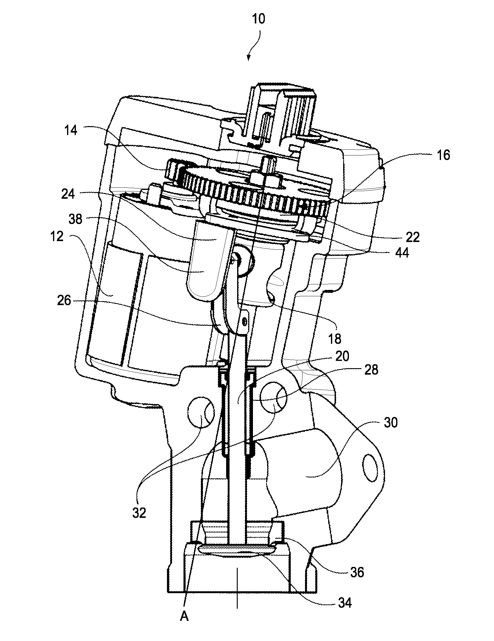
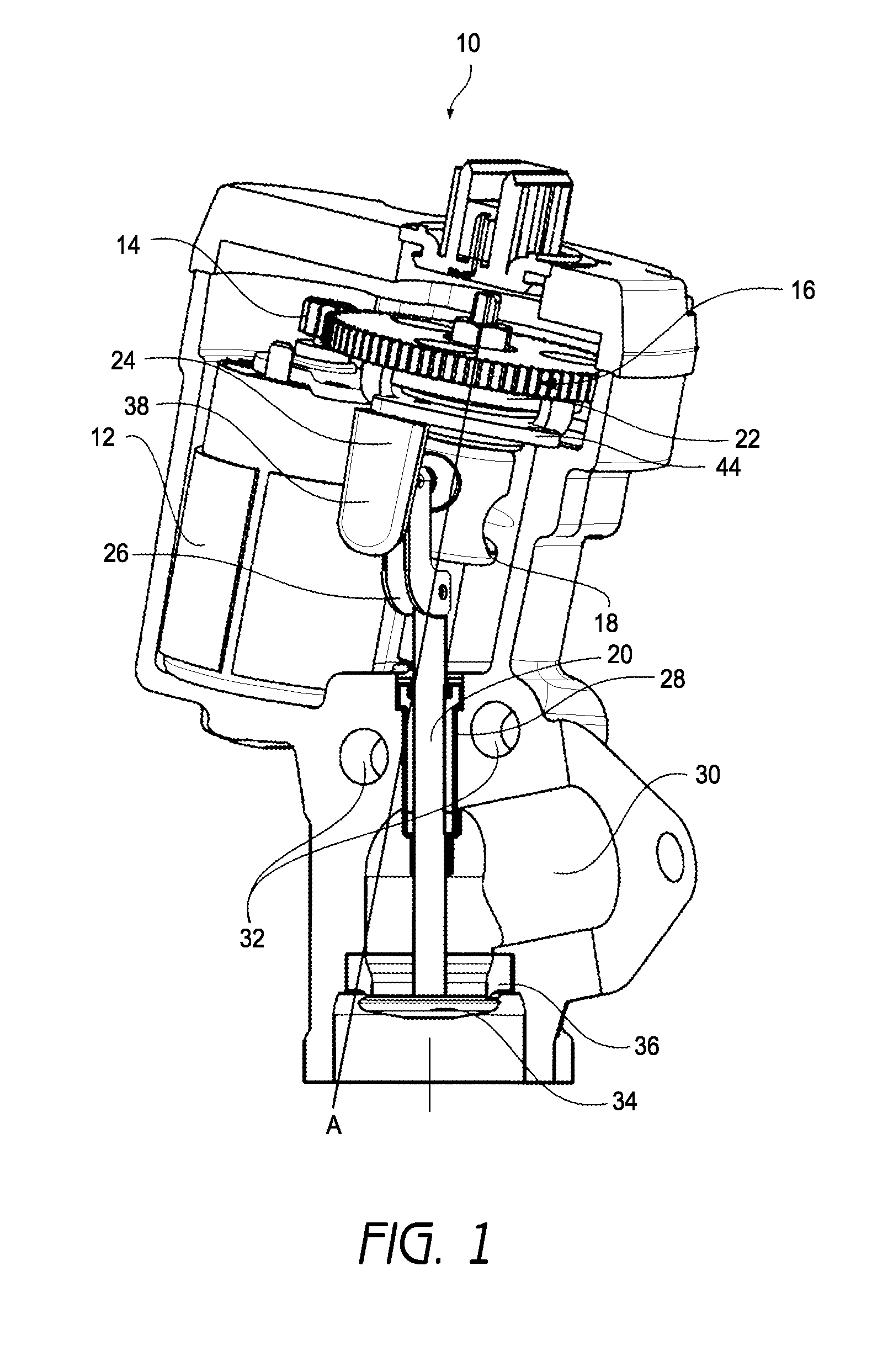
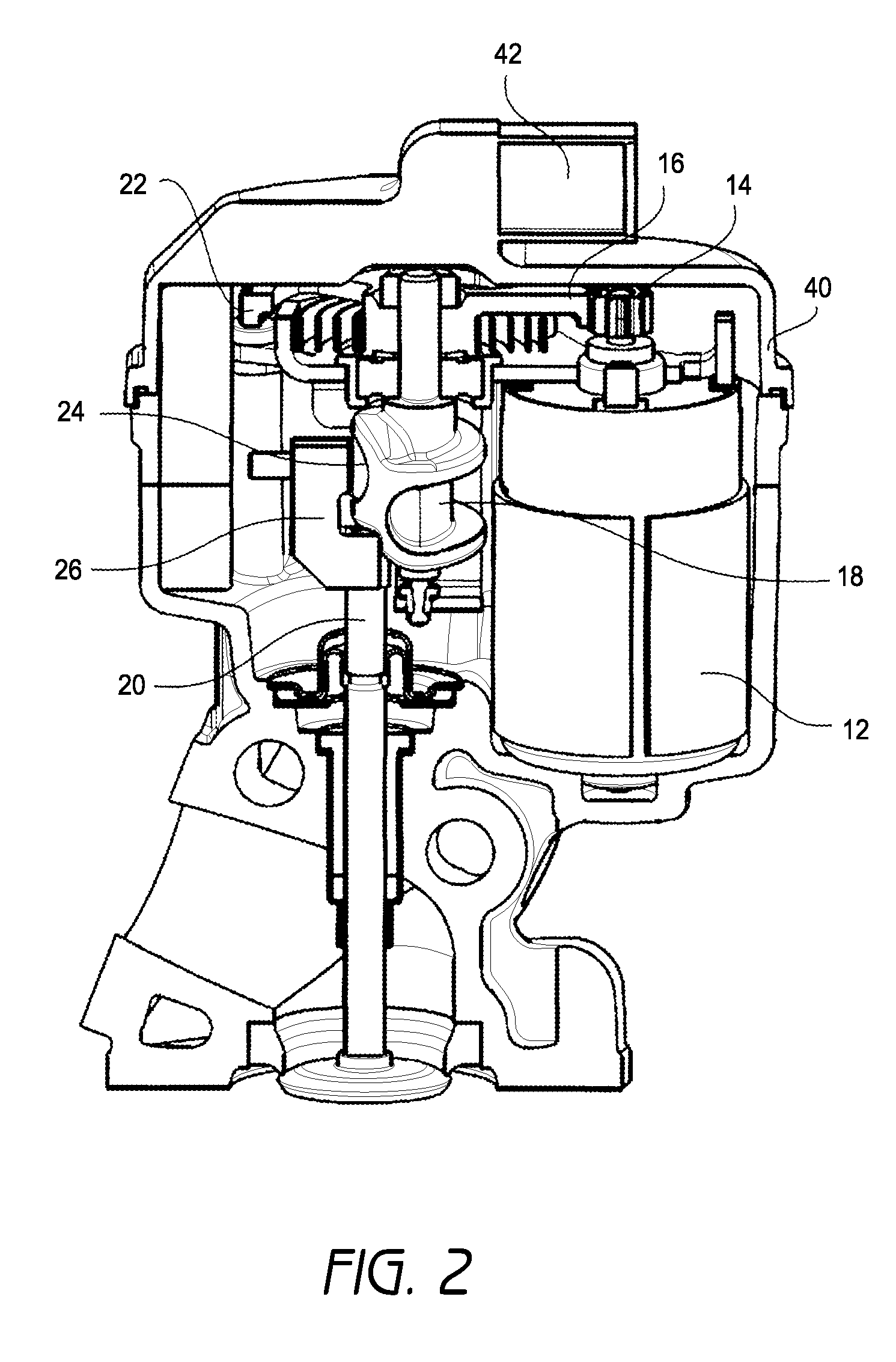
[0022]As can be seen from FIG. 1, the exhaust gas recirculation valve 10 according to the invention comprises a drive 12 in the form of an inclined motor. In the illustrated embodiment, a pinion 14 is arranged on the motor shaft and drives a gear 16. The drive element 18 in the form of a worm gear (or worm) is attached to the gear 16 and drives the valve tappet 20 as described in more detail below. In the illustrated embodiment, as can be seen in more detail from FIG. 2, the worm comprises an axis A that is supported both at its upper end and at its lower end. In the illustrated embodiment, the arrangement of gear 16 and worm 18 is connected to a coil spring 22 which is solely twisted upon opening and closing of the valve. In the illustrated embodiment, the combination of pinion 14 and gear 16 corresponds to a single-stage transmission having the above-described advantages.

[0023]The conversion of the rotary motion of the worm 18 into a translational motion of the valve tappet 20 is ...


PUM


Abstract

An exhaust gas recirculation valve comprises a drive, at least one rotatable drive element and at least one translationally drivable driven element. The drive element comprises a thread element that is configured to convert rotational motion of the drive element into translation of the driven element. A rotational axis of the drive element is inclined with respect to a translational axis of the driven element.

Description

CROSS-REFERENCE TO RELATED APPLICATIONS[0001]This application is related to, and claims priority from, European Patent Application No. 08 165 906.2, filed Oct. 6, 2008, entitled “EXHAUST GAS RECIRCULATION VALVE,” the entirety of which is incorporated by reference herein and made a part of the present specification.BACKGROUND OF THE INVENTION[0002]1. Field of the Invention[0003]The invention concerns an exhaust gas recirculation valve. In the field of combustion engines, it is known to recirculate exhaust gas toward the fresh air side depending on operating conditions in order to reduce fuel consumption and noxious emissions.[0004]2. Description of the Related Art[0005]From EP 1 111 227 A2 an exhaust gas recirculation valve is known in which the rotary motion of a drive motor is converted into a translational motion of the valve element. At least at the beginning of the opening operation the valve element is given a rotary motion.[0006]EP 1 526 271 A1 concerns an exhaust gas recircul...

Claims


Application Information

Patent Timeline
Patent Type & Authority Applications(United States)
IPC IPC(8): F16K31/44
CPCF02M25/0701F02M25/0724Y02T10/121F02M25/0789F02M25/0773F02M26/21F02M26/50F02M26/54F02M26/67F16K27/02F16K31/02
Inventor KLIPFEL, BERNHARDTHIERY, CHRISTOPH
Owner HANON SYST
Why Eureka
Try Eureka