Manufacturing method of three-dimensionally shaped object

a manufacturing method and three-dimensional shape technology, applied in the direction of additive manufacturing process, electric/magnetic/electromagnetic heating, instruments, etc., can solve the problems of insufficient correction of irradiation point of light beams, and insufficient correction of irradiation poin

Inactive Publication Date: 2010-07-15
PANASONIC CORP
View PDF4 Cites 65 Cited by
  • Summary
  • Abstract
  • Description
  • Claims
  • Application Information

AI Technical Summary

Benefits of technology

[0008]The present invention is conceived to solve the above mentioned problems and purposed to provide a manufacturing method of three-dimensionally shaped object by which correction of irradiation points of light beams can be performed easily.

Problems solved by technology

Thus, correction of the irradiation points of the light beams cannot be corrected sufficiently.
In the manufacturing method shown in the patent document 1, contrast of the traces of the light beams, however, is obscure, so that irradiation points cannot be corrected sufficiently.

Method used


Image

  • Manufacturing method of three-dimensionally shaped object
  • Manufacturing method of three-dimensionally shaped object
  • Manufacturing method of three-dimensionally shaped object

Examples


first embodiment

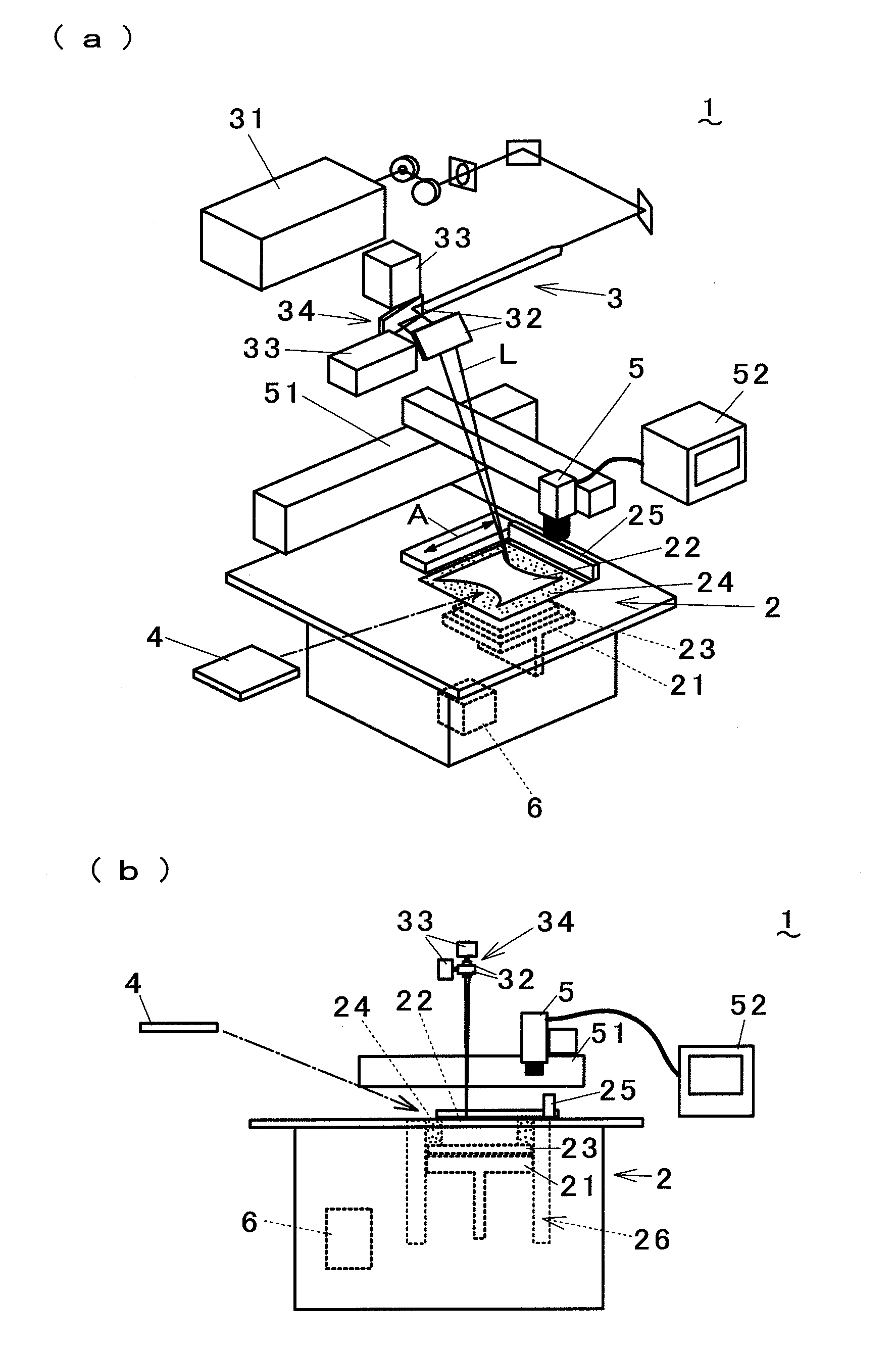
[0016]A manufacturing method of three-dimensionally shaped object in accordance with a first embodiment of the present invention is described with reference to drawings. FIGS. 1(a) and 1(b) respectively show a configuration of equipment for metal-laser sintering process used in the manufacturing method, and illustration of a part of a light irradiation unit is omitted in FIG. 1(b). The equipment for metal-laser sintering process 1 comprises a powder layer forming unit 2 which spreads metal powder as a layer having a predetermined thickness, a light irradiation unit 3 which outputs light beams L and irradiates the light beams at arbitrary points, and a control unit 6 which controls each unit of the equipment for metal-laser sintering process 1. The powder layer forming unit 2 has a lifting table 21 which moves up and down, a substrate 23 which is disposed on the lifting table 21 and serves as a base of a shaped object 22, a wiper 25 which moves in a direction shown by arrow A and spr...

second embodiment

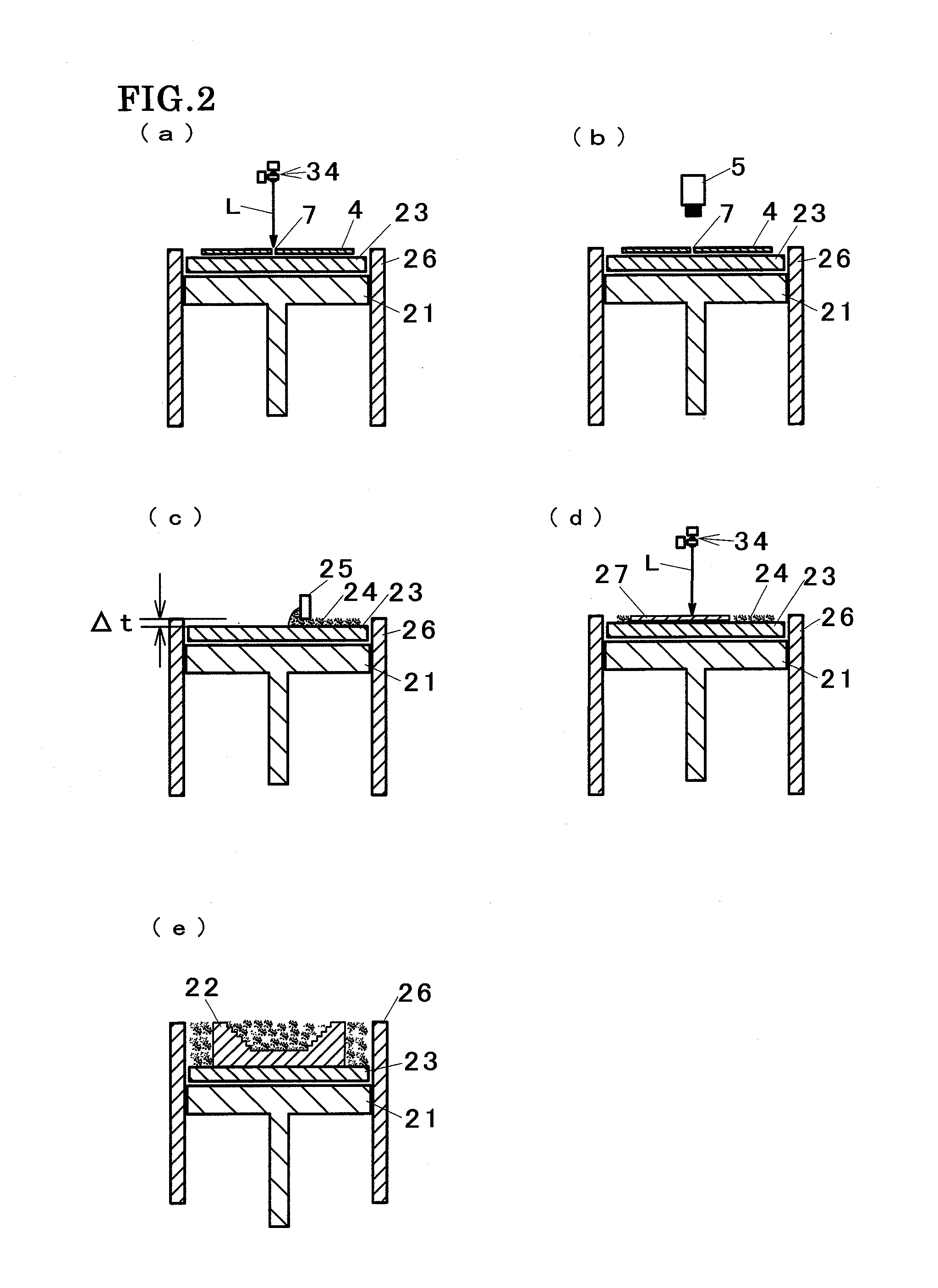
[0026]Correction of the irradiation points of the light beams in the manufacturing method of three-dimensionally shaped object in accordance with a second embodiment of the present invention is described with reference to drawings. FIGS. 5(a) and 5(b) respectively show conditions that the imaging camera 5 takes an image of the correction mark 7 formed on the correction target 4. The correction target 4 is disposed on a correction plate 41 having a cavity which clarifies the contrast of the correction mark 7, and the cavity is a counter bore 41a in FIG. 5(a), and the cavity is a through hole 41b in FIG. 5(b). FIG. 6(a) shows a plain view of a correction plate on which the correction target 4 is disposed, and FIG. 6(b) shows a condition of the correction target 4 disposed on the correction plate 41.

[0027]In this embodiment, the correction plate 41 is disposed on the substrate 23, and the correction target 4 is disposed on the correction plate 41. Cavities are formed on the correction ...

third embodiment

[0029]Correction of the irradiation points of the light beams in the manufacturing method of three-dimensionally shaped object in accordance with a third embodiment of the present invention is described with reference to drawings. FIG. 7(a) shows a condition that an image of the correction mark 7 located above the counter bore 41a is taken, and FIG. 7(b) shows a condition that an image of the correction mark 7 located above the through hole 41b. In this embodiment, the equipment for metal-laser sintering process 1 comprises an illumination unit 8, and takes an image of the correction mark 7 with illumination by the illumination unit 8. The illumination unit 8 is an incandescent lamp or LEDs, for example. Alternatively, it is preferable to use optical fibers to propagate external lights for irradiation. Even when the cavity on the correction plate 41 is the counter bore 41a, as shown in FIG. 7(a), or even when the cavity on the correction plate 41 is the through hole 41b, as shown in...


PUM

PropertyMeasurementUnit
thicknessaaaaaaaaaa
poweraaaaaaaaaa
cross-shapeaaaaaaaaaa

Abstract

An equipment for metal-laser sintering process includes a powder layer forming unit, an irradiation unit which irradiates light beams, a correction target on which a correction mark serving as a fiducial in correction of the irradiation points of the light beams is formed, and an imaging camera which takes an image of the correction mark. The correction target is formed of a material which is melted by irradiation of light beam so as to be formed a through hole. The correction target is disposed on the substrate and the light beams are irradiated to penetrate the correction target so that the correction mark is formed. Subsequently, the imaging camera takes an image of the correction mark and the location of the correction mark is measured, and thus, correction of the irradiation points is performed. Since the correction mark is formed to be a through hole, contrast becomes clear so that location of the correction mark can be measured easily, and the correction of the irradiation points of the light beams can be performed easily.

Description

TECHNICAL FIELD[0001]The present invention relates to a manufacturing method of three-dimensionally shaped object by irradiating light beams to an inorganic or an organic pulverized material.BACKGROUND ART[0002]A manufacturing method of three-dimensionally shaped object is conventionally known that light beams are irradiated on a powder layer formed of an inorganic or an organic pulverized material so as to form a sintered layer by melting the powder layer, and repeating processes of forming a new powder layer on the sintered layer and irradiation of light beams. In such a manufacturing method, a CO2 laser is mainly used as a light source of the light beams.[0003]Since the CO2 laser is a gas laser, alignment of a resonance mirror of a light beam oscillator inside delicately changes due to fever with laser oscillation, and thus, characteristics such as divergence angle of the light beams, stability of optical axis of the light beams, and stability of the laser output power may vary. ...

Claims


Application Information

Patent Timeline
Patent Type & Authority Applications(United States)
IPC IPC(8): B29C35/08
CPCB29C67/0077B22F3/1055B29C64/153B33Y10/00Y02P10/25B22F10/28B22F12/42B22F12/90B22F12/41B22F12/224B29C67/00B29C67/04C04B35/64B29C35/08
Inventor HIGASHI, YOSHIKAZUABE, SATOSHI
Owner PANASONIC CORP
Why Eureka
Try Eureka