
Supplemental scene reference surface devices for three-dimensional mapping

a three-dimensional mapping and reference surface technology, applied in the field of computerized modeling of three-dimensional objects, can solve the problems of inability to stitch together the 3d model and the incomplete portion of the 3d model, and achieve the effect of more accurate positioning information

Active Publication Date: 2010-07-15
DENSYS
View PDF10 Cites 8 Cited by
  • Summary
  • Abstract
  • Description
  • Claims
  • Application Information

AI Technical Summary

Benefits of technology

[0020]It is a goal of the present invention to extend the 3D modeling capabilities of imaging systems, such as those employing structured illumination. It is also a goal of the present invention to provide more accurate positioning information for imaging systems, including, but not limited to those employing structured illumination.
[0021]To attain these goals, embodiments of the present invention provides for supplemental reference surface devices to increase the richness of the intra-oral scene in a calibrated fashion that facilitates determining the precise 3D positions of intra-oral features and the stitching together of separate tiles by providing increased imaged area.
[0022]Embodiments of the present invention also facilitate determining the angulation and position of intra-oral features, such as abutments, teeth, false teeth and other prosthetic elements.
[0024]The reference surface device of the present invention allows for the stitching together of separate tiles of very small areas within the mouth, such as a single tooth, or an abutment. Additionally, the reference surface device may be used for imaging of the entire inner mouth.

Problems solved by technology

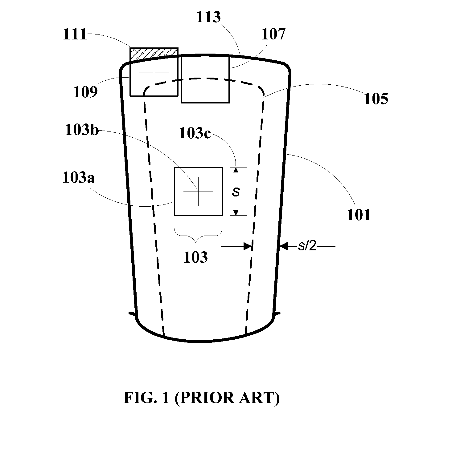
A restriction in using the above-described structured illumination method, however, results from the fact that the projected light patterns have a two-dimensional (herein also denoted as “2D”) extent over the scene surfaces.
As a consequence, there are limitations in the 3D models of intra-oral scenes produced by such a method.
That is, a 3D model typically must be constructed from the results of a set of separate imaging operations performed in different positions and / or in different directions, each of which results in an incomplete portion of a 3D model.
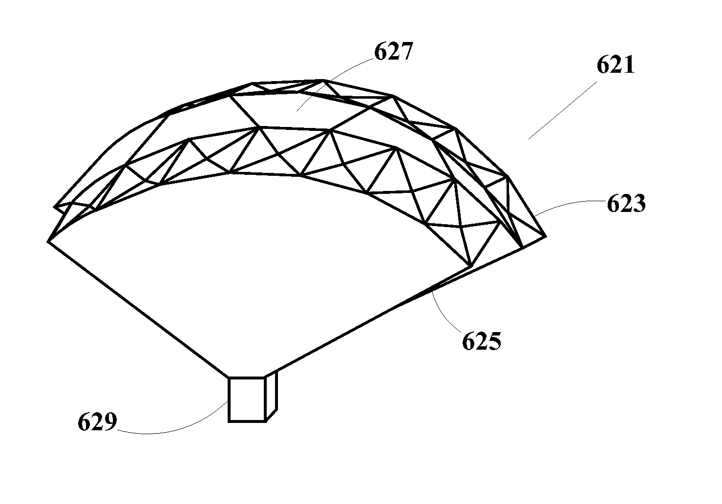
If the separate 3D model tiles do not have such common features, there is typically no way to stitch them together to obtain a unified 3D model.
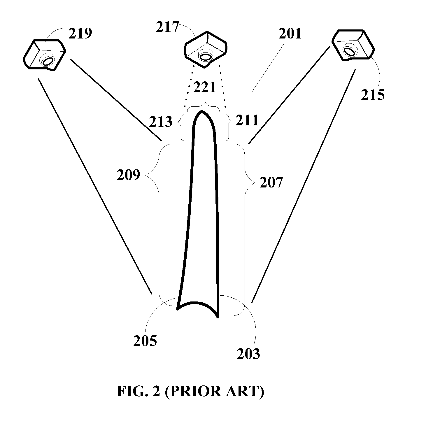
However, because of the edge imaging and surface area limitations as discussed above, a region 211 and a region 213 adjacent to the edge of the tooth's occlusal surface cannot be satisfactorily imaged.
Thus, the use of structured illumination for intra-oral 3D imaging may result in discontinuities that make stitching difficult or impossible.
Small objects and other special intra-oral features often lack sufficient surface area for satisfactory 3D reconstruction from projection of structured illumination patterns.
Even if 3D reconstruction is achieved, there may be insufficient 3D area in the tile to enable stitching to another tile.
In this manner, structured illumination cannot be used to determine the precise position of abutment 307, and this is another limitation of the methodology.

Method used


Image

  • Supplemental scene reference surface devices for three-dimensional mapping
  • Supplemental scene reference surface devices for three-dimensional mapping
  • Supplemental scene reference surface devices for three-dimensional mapping

Examples


Embodiment Construction

[0112]The principles and operation of a method according to the present invention may be understood with reference to the drawings and the accompanying description.

Reference Surface Device for Locating the Position of an Intra-Oral Feature

[0113]In the detailed description, numerous specific details are set forth in order to provide a thorough understanding of the invention. However, it will be understood by those skilled in the art that these are specific embodiments and that the present invention may be practiced also in different ways that embody the characterizing features of the invention as described and claimed herein.

[0114]FIG. 4 illustrates a reference surface device 400 according to an embodiment of the present invention, having position and orientation indicia, for precisely locating the position of an intra-oral feature. These indicia provide precise optical reference points for determining the location of a specific point in the intra-oral scene, such as a point on an in...


PUM


Abstract

Supplemental reference surface devices are provided for use in three-dimensional modeling of intra-oral scenes using identifiable positional characteristics from structured illumination or other techniques. Reference surface devices having at least one substantially plane smooth non-polished face are disclosed for locating the positions of intra-oral features, and for stitching together separate 3D tiles according to the identifiable positional characteristics. Reference surface devices include a mounting point of known position relative to the faces, which can be attached to an intra-oral feature in or adjacent to the imaged intra-oral scene. Disclosed are reference surface devices having orientation and position indicia, as well as reference surface devices having a multiplicity of faces distributed in spatial position and angular orientation to facilitate correlation of 2D images obtained by imaging systems in different positions. Sizes of the faces of reference surface devices are optimized for resolving patterns of identifiable positional characteristics while providing suitable spatial and angular distributions.

Description

CROSS REFERENCE TO RELATED APPLICATIONS[0001]This application claims the benefit of priority to U.S. Patent Application Ser. No. 60 / 937,048, filed on Jun. 26, 2007, entitled “Supplemental Scene Reference Surfaces For Three-Dimensional Mapping” and incorporated herein in its entirety by reference.FIELD OF THE INVENTION[0002]The present invention relates to computerized modeling of three-dimensional objects, and, more particularly, to apparatus and methods for supplementing scenes with reference surface devices for improved model rendering.BACKGROUND OF THE INVENTION[0003]A common method of making a three-dimensional (herein also denoted as “3D”) mathematical model of the surfaces of a scene is to project light reference patterns onto the scene, take an image of the scene showing the projected patterns (herein referred to as “structured illumination”), and then analyze the imaged patterns in comparison with an image of the same patterns projected onto a plane surface. By precisely mea...

Claims


Application Information

Patent Timeline
IPC IPC(8): A61B6/00
CPCA61B5/0073A61B5/0084A61B5/0088G01B11/24A61B2019/505A61B2019/5295A61C9/004A61B5/706A61C9/006A61B2090/367G01B11/2513A61B2034/105G06T7/70G06T7/73G06T2207/30036
Inventor ERNST, MAURICE MOSHE
Owner DENSYS
Learn More