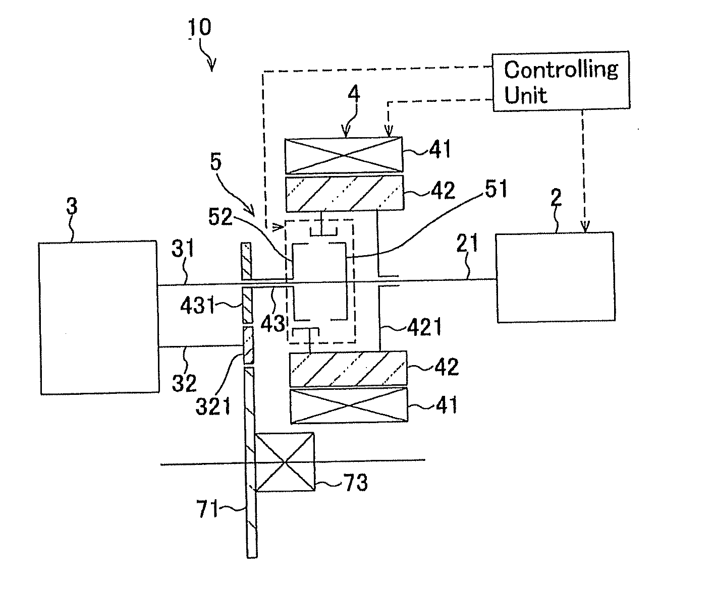
[0020]In the invention that is directed to claim 1, it is possible to adapt it into a construction in which the rotary electric device is connected to an upstream side of the multistaged change-speed mechanism, and to a downstream side thereof, because a rotor of the rotary electric device can be connected to the input shaft of the multistaged change-speed mechanism (i.e., on the upstream side) by way of the first power interrupting mechanism, and because the rotary-electric-device-side output shaft can be connected to the rotor of the rotary electric device by way of the second power interrupting mechanism on an output-shaft side of the multistaged change-speed mechanism (i.e., on the downstream side). It is possible to materialize a power transmission apparatus with both of the following characteristics: it is possible to make use of the rotary electric device for starting the internal
combustion engine when the rotary electric device is connected to the upstream side; and it is possible to make use of the rotary power, which is output from the rotary electric device, as a
motive power without intervening the multistaged change-speed mechanism when it is connected to the downstream side; and the like. And, by sharing the starting of the internal
combustion engine and the generation of
electricity with the rotary electric device, it becomes feasible to downsize the
starter and
alternator, or to omit them, so that the costs can be suppressed. Besides that, at the time of traveling where the internal combustion engine runs efficiently, both of the first power interrupting mechanism and second power interrupting mechanism are disconnected, and then the giving and receiving of the
motive power to and from the rotary electric device are turned off, and accordingly it is also possible to avoid the loss of
electricity or driving force, and consequently it is possible to drive with good fuel-consumption performance depending on traveling conditions.
[0021]In the invention that is directed to claim 2, it is possible to suppress the overall length from enlarging so that it can be constructed compactly, because it is possible to adapt it into a power transmission mechanism, in which the first and second power interrupting mechanisms are put in place on an inner side of the rotary electric device, even when the rotary electric device and power interrupting mechanisms are added.
[0022]In the invention that is directed to claim 3, it is possible to adapt it into a construction in which the input shaft of the multistaged change-speed mechanism, and the output shaft are close to the rotor of the rotary electric device, to which they are connected by way of the first or second power interrupting mechanisms, by disposing the input shaft and output shaft of the multistaged change-speed mechanism to protrude toward an output side of the rotary electric device when connecting the rotary electric device to the upstream and downstream sides of the multistaged change-speed mechanism. That is, although the construction gets complicated in order to connect the rotor of the rotary electric device to a distant shaft because the rotor of the electric device gets away from one of the input and output shafts when it is close to the other one of them, it is possible to avoid the construction from getting complicated by means of disposing both of the shafts to protrude toward a side in the same direction. Hence, even when connecting the rotor of the rotary electric device to the upstream and downstream sides, the construction does not get complicated, but it can be constructed compactly.
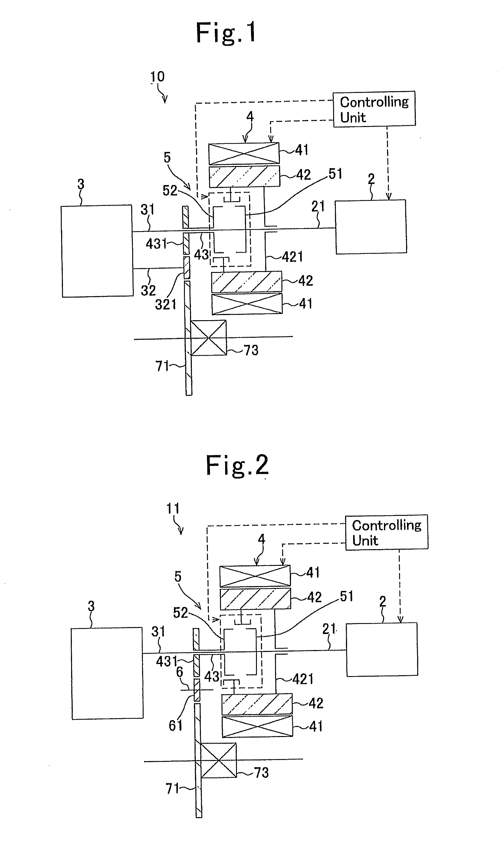
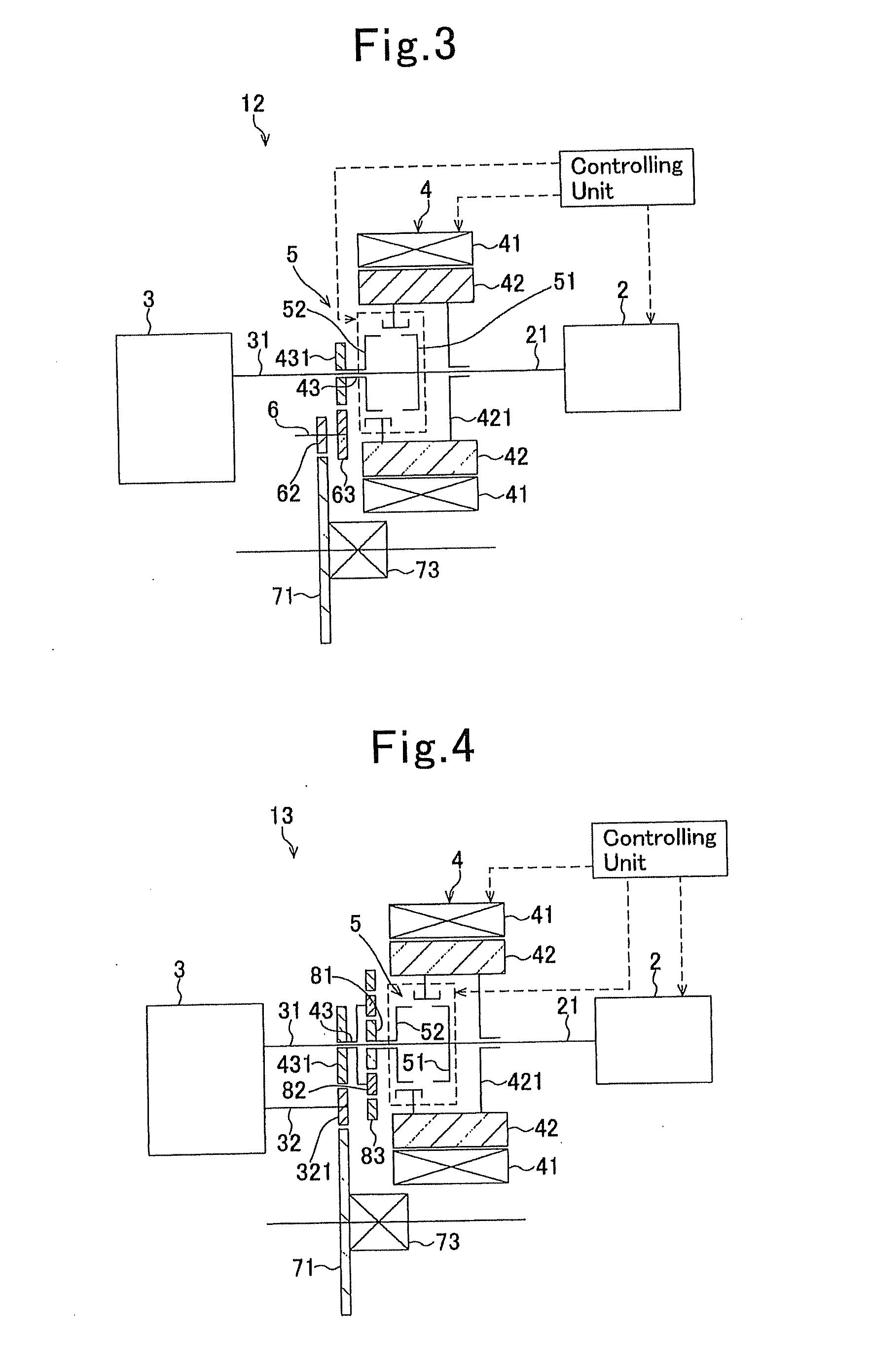
[0023]In the invention that is directed to claim 4, it is possible to increase the degree of freedom on gear ratios for transmitting a power from the rotor of the rotary electric device to the final deceleration gear by adding a shaft, which is put in place parallel to the output shaft of the internal combustion engine and the input and output shafts of the multistaged change-speed mechanism, and then by putting one or more transmission gears onto that additional shaft. Moreover, it is possible to adjust the rotary direction of rotary power that is transmitted to the final deceleration gear by adding the shaft. For example, general multistaged change-speed mechanisms exhibit rotary directions between the input shaft and the output shaft that become opposite to each other. As a result, since a rotary direction of the final deceleration gear, which is coupled to the output shaft, becomes the same direction as that of the input shaft of the multistaged change-speed mechanism, it is not possible to transmit a rotary power from the rotary-electric-device-side output gear to the final deceleration gear directly in a case where a rotary direction of the rotary-electric-device-side output shaft is made identical to that of the input shaft of the multistaged change-speed apparatus. Hence, it is possible to reverse the rotary direction of a rotary power to be transmitted by adding the additional shaft between the two, and then it is possible to carry out the transmission of the rotary power from the rotary-electric-device-side output shaft to the final deceleration gear smoothly.
[0024]In the invention that is directed to claim 5, it is possible to increase the degree of freedom on gear ratios by putting a planetary gear mechanism, which comprises a sun gear, a planetary gear and a ring gear, in place on a side of the rotary-electric-device-side output shaft. Compared with the construction as set forth in claim 4 in which a shaft is added and then a transmission gear is put in place onto that additional shaft, it is possible to increase the degree of freedom on gear ratios furthermore.
[0025]In the invention that is directed to claim 6, it further comprises a counter shaft other than the input shaft and output shaft, and the counter shaft is disposed to protrude toward a side of the rotary electric device along with the input shaft. And, an output of the rotary electric device can be input to the counter shaft, and can then be transmitted to the output shaft. Hence, even in such power transmission mechanisms with the construction in which a rotary power being input to the input shaft is transmitted to the output shaft by way of the counter shaft, it is possible to adapt those easily into a construction that comprises both a rotary electric device and an internal combustion engine by adding a rotary electric device and one pair of gears.

