Pressure Sensing System For A Planter
- Summary
- Abstract
- Description
- Claims
- Application Information
AI Technical Summary
Benefits of technology
Problems solved by technology
Method used
Image
Examples
Embodiment Construction
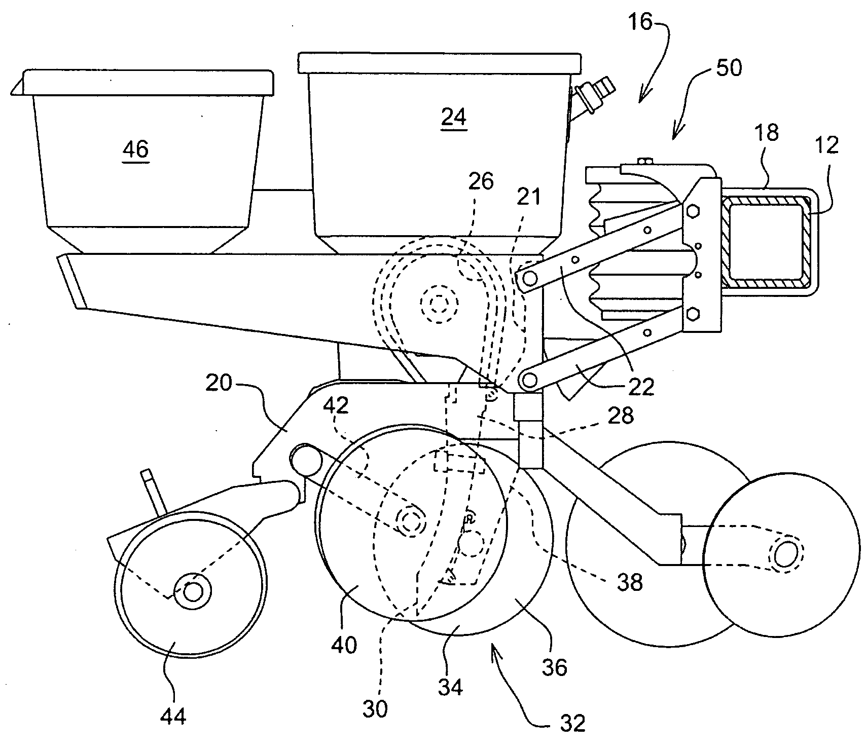
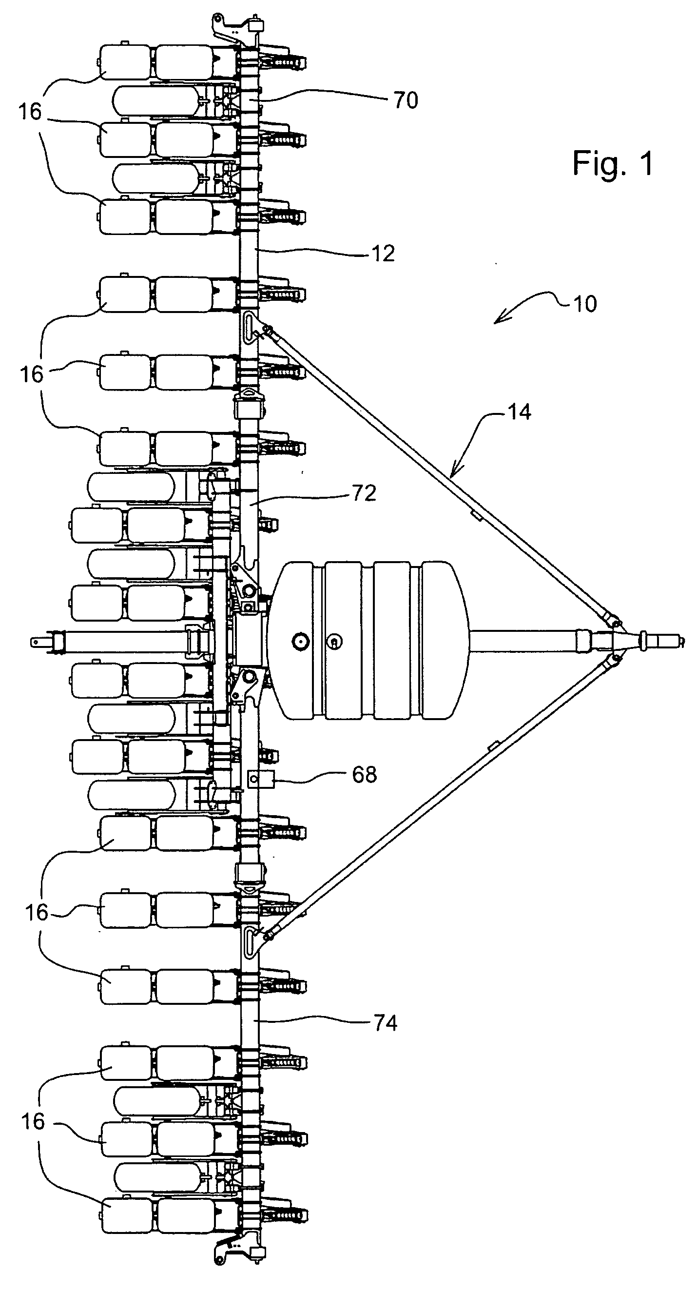
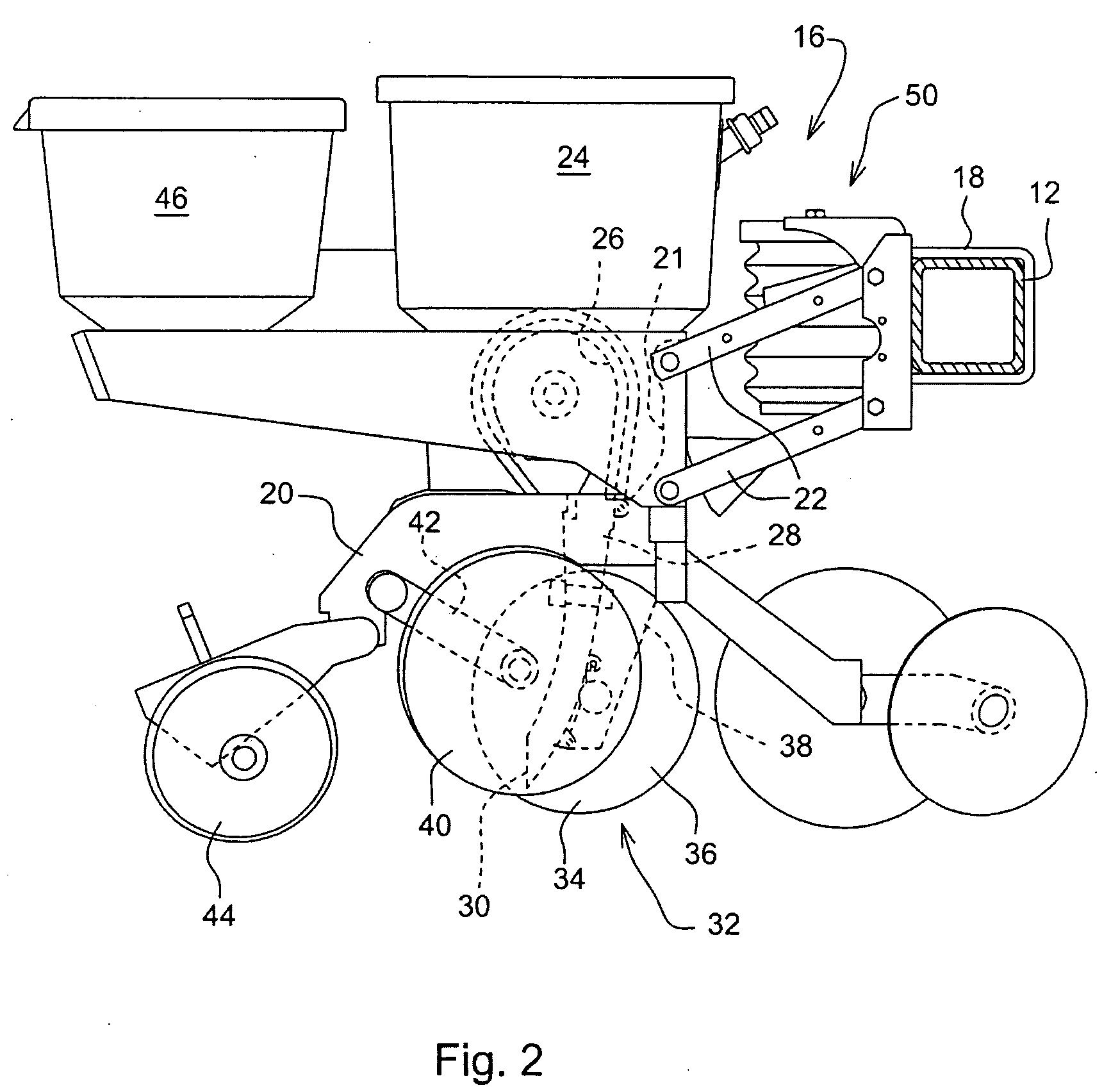
[0009]With reference to FIG. 1, an example planter 10 is shown containing the down force pressure sensor system of the present invention. Planter 10 includes a tool bar 12 as part of a planter frame 14. Mounted to the tool bar are multiple planting row units 16. Row units 16 are typically identical for a given planter but need not be identical. A row unit 16 is shown in greater detail in FIG. 2. The row unit 16 is mounted to the tool bar 12 by U-bolts 18. The row unit 16 is provided with a central frame member 20 having a pair of upwardly extending arms 21 at the forward end thereof. The arms 21 connect to a parallelogram linkage 22 for mounting the row unit 16 to the tool bar 12 for up and down relative movement between the unit 16 and toolbar 12 in a known manner. Seed is stored in seed hopper 24 and provided to seed meter 26. From the seed meter 26 the seed is dropped through a seed tube 28. The lower end 30 of the seed tube is positioned just above a seed trench formed by a tren...
PUM
 Abstract
Description
Claims
Application Information
 - R&D
- Intellectual Property
- Life Sciences
- Materials
- Tech Scout
- Unparalleled Data Quality
- Higher Quality Content
- 60% Fewer Hallucinations
Browse by: Latest US Patents, China's latest patents, Technical Efficacy Thesaurus, Application Domain, Technology Topic, Popular Technical Reports.
© 2025 PatSnap. All rights reserved.Legal|Privacy policy|Modern Slavery Act Transparency Statement|Sitemap|About US| Contact US: help@patsnap.com


