Increasing the angular range of light collection in solar collectors/concentrators

a technology of solar collectors and concentrators, applied in the field of light collectors and concentrators, can solve the problems of low efficiency in converting light energy into heat or electricity, inability to overcome the variation in the amount of solar energy received, and the system employing lenses/mirrors tends to be bulky and heavy

Inactive Publication Date: 2010-07-22
SNAPTRACK
View PDF101 Cites 46 Cited by
  • Summary
  • Abstract
  • Description
  • Claims
  • Application Information

AI Technical Summary

Benefits of technology

[0009]Various embodiments described herein comprise light guides for collecting/concentrating ambient light and directing the collected light to a photocell. The light guide may include one or more holographic layers disposed forward to the light guide. The holographic layers may comprise volume holograms or surface relief features. The holographic layers may turn light incident at a first angle and redirect incident light at a second angle towards a plurality of prismatic features. The prismatic features may be disposed rearward to the light guide. Light incident on the prismatic features may be further redirected so as to propagate the ligh...

Problems solved by technology

Major drawbacks in using solar energy as a reliable source of renewable energy are low efficiency in converting light energy to heat or electricity and the variation in the solar energy depending on the time of the day and the month of the year.
Other types of lenses and mirrors can also be used to significantly increase the convers...

Method used


Image

  • Increasing the angular range of light collection in solar collectors/concentrators
  • Increasing the angular range of light collection in solar collectors/concentrators
  • Increasing the angular range of light collection in solar collectors/concentrators

Examples


embodiment 100

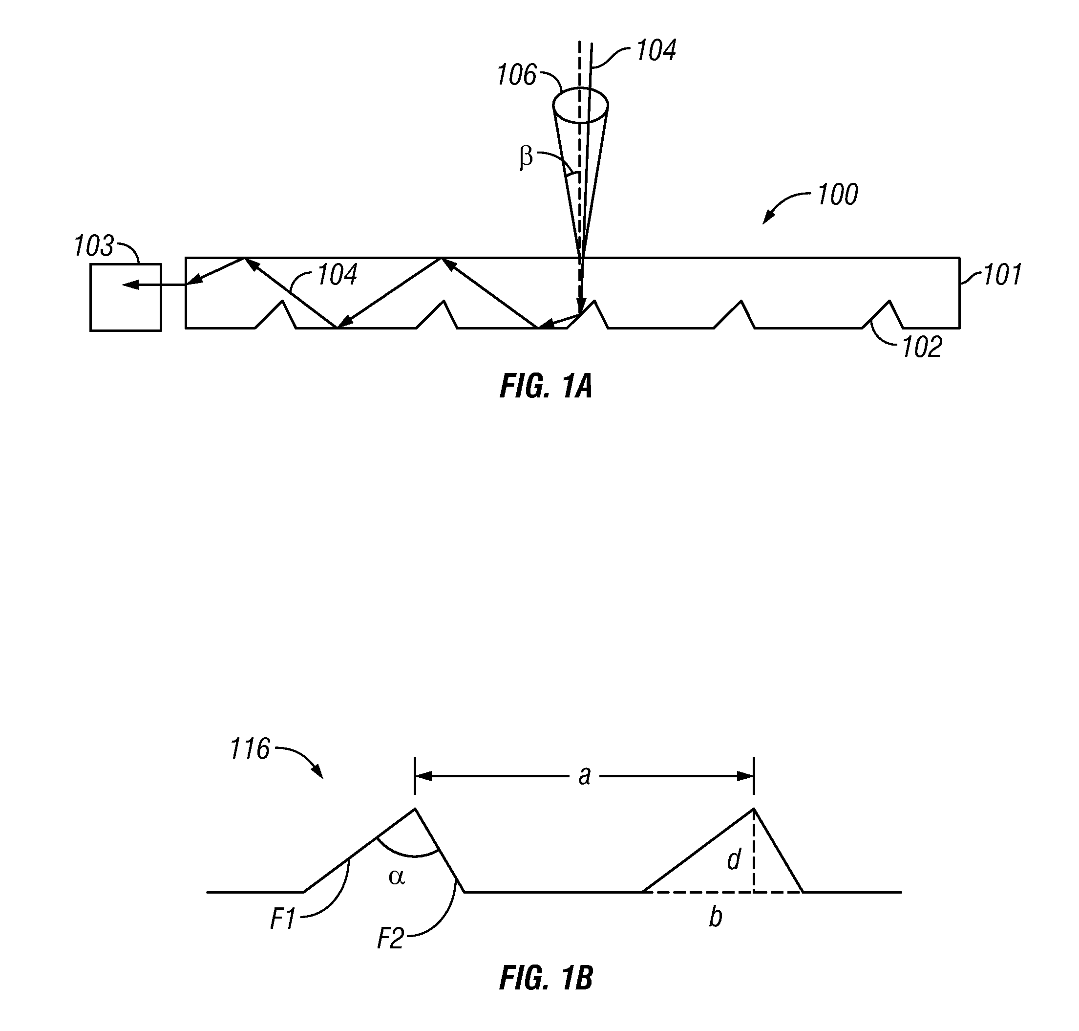
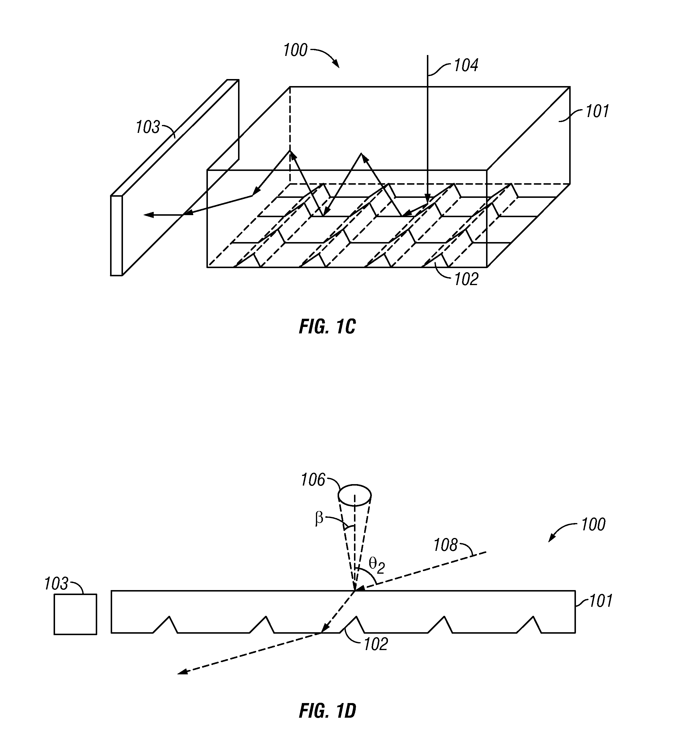
[0038]One embodiment of a prismatic light guide used to couple ambient light into a photo cell is shown in FIG. 1A. The photo cell may be a photovoltaic cell or a photo detector. FIG. 1A illustrates the side view of an embodiment 100 comprising a light guide 101 disposed with respect to a photo cell 103. In some embodiments, the light guide 101 may further comprise a substrate (not shown). A plurality of prismatic features 102 may be disposed in the light guide 101. The light guide 101 may comprise a top and bottom surface including a plurality of edges therebetween. In the embodiment illustrated in FIG. 1A the prismatic features are disposed on the bottom surface. Light incident on the light guide 101 may be redirected into the light guide 101 by the plurality of prismatic features 102 and guided within the light guide 101 by multiple total internal reflections at the top and bottom surface. The light guide 101 may comprise optically transmissive material that is transparent to rad...

embodiment 2000

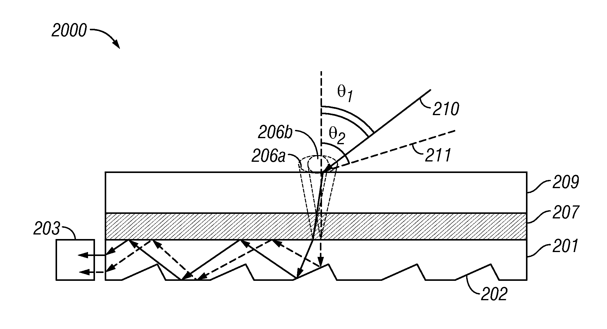
[0048]FIG. 2A illustrates an embodiment 2000 comprising a prismatic light guide 201. Prismatic features 202 are disposed rearward of the prismatic light guide 201. The embodiment further comprises an angle turning layer 209 disposed forward of light guide 201. In some embodiments, the angle turning layer 209 may comprise a holographic layer. In some embodiments, the angle turning layer 209 may comprise volume features (e.g. volume holograms). In some embodiments, the angle turning layer 209 may comprise surface relief features (e.g. surface relief diffractive features that form surface holograms or surface diffractive optical elements, etc). In some embodiments, the angle turning layer may comprise volume features and surface relief diffractive features. In some embodiments, the prismatic light guide 201 and the angle turning layer 209 may be laminated together. The angle turning layer 209 may be joined to the prismatic light guide 201 with an adhesive layer 207. In some embodiments...

embodiment 2010

[0051]The angle turning layer 209 may comprise a first set of volume, surface relief features or a combination thereof that are configured to turn the rays of light incident at a first angle to a second angle. In various embodiments, the second angle can be more normal than the first angle. The angle turning layer 209 may comprise a second set of volume, surface relief features or a combination thereof that are configured to turn the rays of light incident at a third angle to a fourth angle. The first and second set of diffractive features may be include in a single angle turning layer 209 or on multiple angle turning layers. For example, in FIG. 2B, the angle turning layer 209 comprises a first set of diffractive features such that ray of light 212 incident on the embodiment 2010 at an angle γ1 is turned by the angle turning layer 209 such that ray 212 is incident on the prismatic light guide 201 at near normal incidence and is subsequently guided within the light guide 201. The gu...


PUM


Abstract

In various embodiments described herein, a device comprises an angle turning layer disposed over a light guiding layer that is optically coupled to a photocell. A plurality of surface features is formed on one of the surfaces of the light guiding layer. The surface features can comprise facets that are angled with respect to each other. The angle turning layer can comprise diffractive features that are volume features or surface-relief features. Light incident on the angle turning layer at a first angle is turned towards the light guiding layer at a second angle and subsequently redirected at a third angle by the surface features of the light guiding layer and guided through the light guide by multiple total internal reflections. The guided light is directed towards a photocell.

Description

CROSS-REFERENCE TO RELATED APPLICATIONS[0001]This application claims priority benefit under 35 U.S.C. §119(e) of U.S. Provisional Application Ser. No. 61 / 098,179 filed on Sep. 18, 2008, titled “INCREASING THE ANGULAR RANGE OF LIGHT COLLECTION IN SOLAR COLLECTORS / CONCENTRATORS” (Atty. Docket No. QMRC.010PR), which is hereby expressly incorporated herein by reference in its entirety.BACKGROUND OF THE INVENTION[0002]1. Field of the Invention[0003]The present invention relates to the field of light collectors and concentrators and more particularly to using micro-structured thin films to collect and concentrate solar radiation.[0004]2. Description of the Related Art[0005]Solar energy is a renewable source of energy that can be converted into other forms of energy such as heat and electricity. Major drawbacks in using solar energy as a reliable source of renewable energy are low efficiency in converting light energy to heat or electricity and the variation in the solar energy depending o...

Claims


Application Information

Patent Timeline
IPC IPC(8): H01L31/00G02B27/42G02B5/32B29D11/00
CPCH01L31/0547Y02E10/52H01L31/054
Inventor GRUHLKE, RUSSELL WAYNEKHAZENI, KASRA
Owner SNAPTRACK
Why Eureka
Try Eureka