Spindle motor, disk drive apparatus using spindle motor, and method of manufacturing spindle motor

a technology of spindle motor and disk drive, which is applied in the direction of sliding contact bearings, rigid support of bearing units, instruments, etc., to achieve the effect of less tim

Inactive Publication Date: 2010-07-22
NIPPON DENSAN CORP
View PDF10 Cites 46 Cited by
  • Summary
  • Abstract
  • Description
  • Claims
  • Application Information

AI Technical Summary

Benefits of technology

[0018]In accordance with the method of manufacturing the spindle motor according to the second preferred embodiment, in a process of inserting the bearing unit inside the holder portion, the adhesive containing the electrically conductive material and the adhesive containing the externally stimulated curing material and/or the anaerobic curing material, at least one of which has the thermosetting p

Problems solved by technology

Examples of such problems that are overcome include a problem in which the adhesive containing the electrically conductive material arranged at or near a lower opening po

Method used


Image

  • Spindle motor, disk drive apparatus using spindle motor, and method of manufacturing spindle motor
  • Spindle motor, disk drive apparatus using spindle motor, and method of manufacturing spindle motor
  • Spindle motor, disk drive apparatus using spindle motor, and method of manufacturing spindle motor

Examples


Embodiment Construction

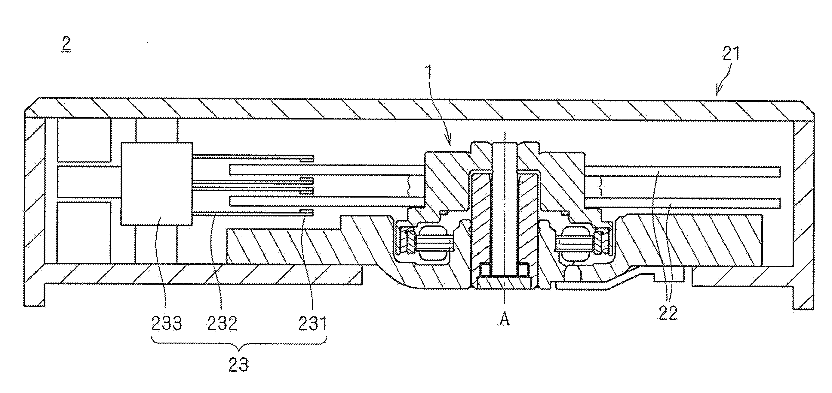
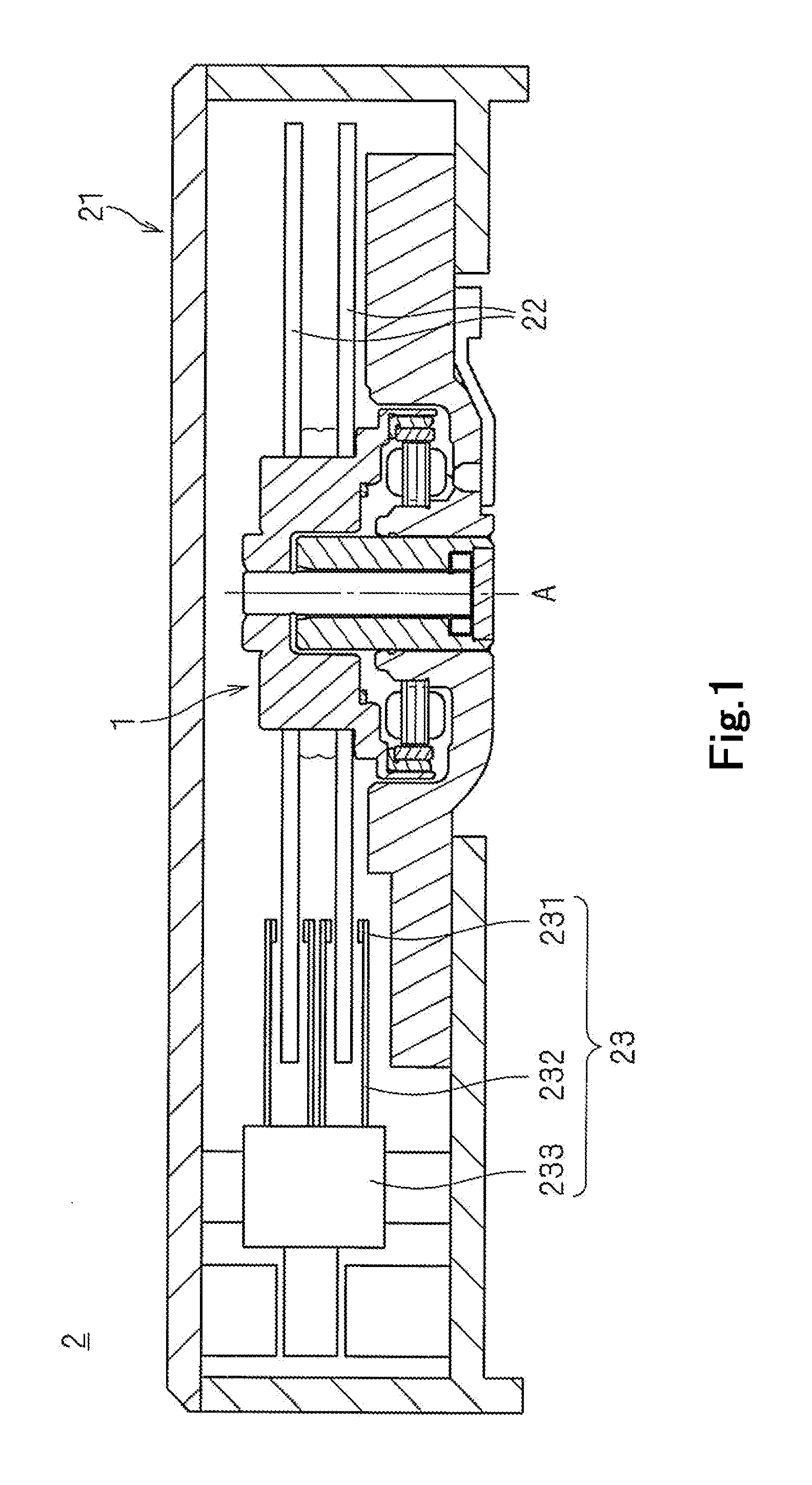
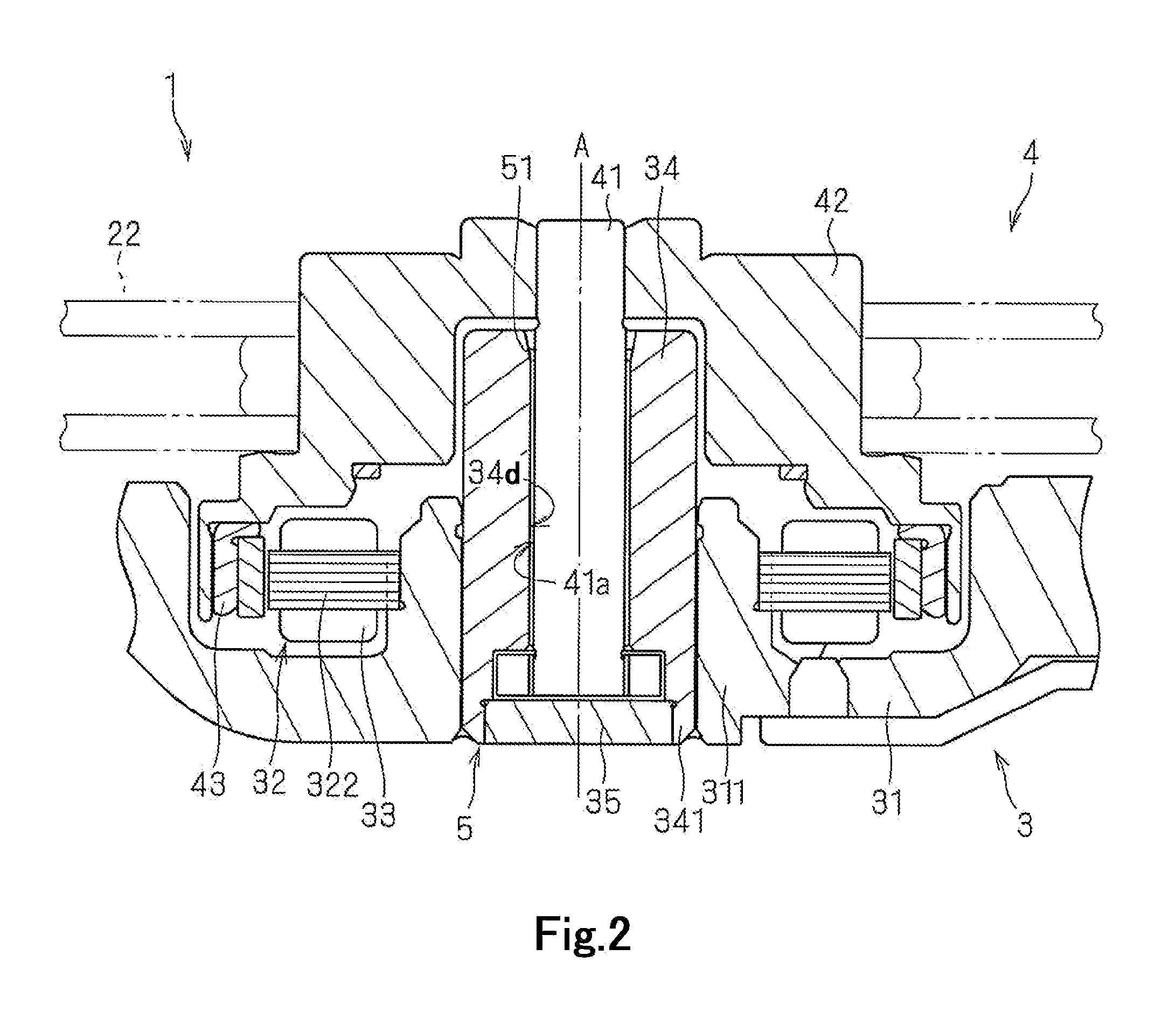
[0027]Hereinafter, preferred embodiments of the present invention will be described with reference to the accompanying drawings. It is assumed herein that an upward / downward direction is defined along a central axis A, and that a side on which a rotating portion 4 is arranged and a side on which a stationary portion 3 is arranged in relation to each other are defined as an upper side and a lower side, respectively. The shape of each member and relative positions of different members will be described based on this assumption. Note that these definitions regarding the upward / downward direction are merely for the sake of convenience in description, and should not be construed to restrict in any way the orientation of a spindle motor or a disk drive apparatus according to any preferred embodiment of the present invention when they are actually installed in a device.

[0028]FIG. 1 is a cross-sectional view of a disk drive apparatus 2 according to a preferred embodiment of the present inve...


PUM

PropertyMeasurementUnit
Lengthaaaaaaaaaa
Lengthaaaaaaaaaa
Particle diameteraaaaaaaaaa

Abstract

A spindle motor includes a shaft arranged in an upward/downward direction along a central axis; a base member including a substantially cylindrical holder portion arranged around the central axis; a bearing unit arranged radially inward of the holder portion; and a rotating portion arranged above the base member to rotate about the central axis. The rotating portion preferably includes a mounting surface on which a disk is to be mounted. An adhesive containing an electrically conductive material and an adhesive containing an externally stimulated curing material and/or an anaerobic curing material are arranged in a clearance space defined between an inner circumferential surface of the holder portion and an outer circumferential surface of the bearing unit. The adhesive containing the electrically conductive material is arranged above the adhesive containing the externally stimulated curing material and/or the anaerobic curing material.

Description

BACKGROUND OF THE INVENTION[0001]1. Field of the Invention[0002]The present invention relates to a spindle motor, a disk drive apparatus using the spindle motor, and a method of manufacturing the spindle motor.[0003]2. Description of the Related Art[0004]Hard disk apparatuses and optical disk apparatuses are typically provided with a spindle motor arranged to rotate a disk about a central axis. The spindle motor includes a stationary portion, which is fixed to a housing of the apparatus, and a rotating portion, which is arranged to rotate with the disk mounted thereon. The spindle motor is arranged to produce torque in a rotation direction centered on the central axis, due to magnetic flux generated between the stationary portion and the rotating portion. In this manner, the rotating portion and the disk mounted on the rotating portion are rotated relative to the stationary portion.[0005]The stationary portion and the rotating portion of the spindle motor are connected to each other...

Claims


Application Information

Patent Timeline
IPC IPC(8): H02K5/16B29C65/52H02K15/14
CPCG11B19/2009Y10T29/49009H02K15/14H02K5/1675F16C17/107F16C35/02F16C2226/40F16C2370/12
Inventor TAMAOKA, TAKEHITOWATANABE, TSUCHITSUGUYAMAMOTO, TAKASHI
Owner NIPPON DENSAN CORP
Why Eureka
Try Eureka