High-pressure discharge lamp comprising a starter antenna

a high-pressure discharge and antenna technology, which is applied in the direction of gas discharge lamp details, gas discharge tubes, electric discharge tubes, etc., can solve the problems of high-pressure discharge lamps, high manufacturing cost of the drive circuit of the lamps, and requires a relatively high drive voltage to start, so as to achieve low starting voltage

Inactive Publication Date: 2010-07-22
KONINKLIJKE PHILIPS ELECTRONICS NV
View PDF14 Cites 9 Cited by
  • Summary
  • Abstract
  • Description
  • Claims
  • Application Information

AI Technical Summary

Benefits of technology

[0005]It is an object of the invention to provide a high-pressure discharge lamp comprising an inner bulb surrounded by an outer bulb for absorbing the ultraviolet radiation from the inner bulb, in which lamp an electric current is supplied to one of the electrodes through a current-supply conductor located outside the outer bulb, and in which the lamp has a relatively low starting voltage which can be reduced in a simple manner without the need of a gastight outer bulb.

Problems solved by technology

In general, a high-pressure discharge lamp of this type has the drawback that it requires a relatively high drive voltage to start the discharge of the gas in the discharge space.
Such a high voltage raises the manufacturing costs of the drive circuit of the lamp.
Moreover, noise may be generated.

Method used


Image

  • High-pressure discharge lamp comprising a starter antenna
  • High-pressure discharge lamp comprising a starter antenna

Examples


Embodiment Construction

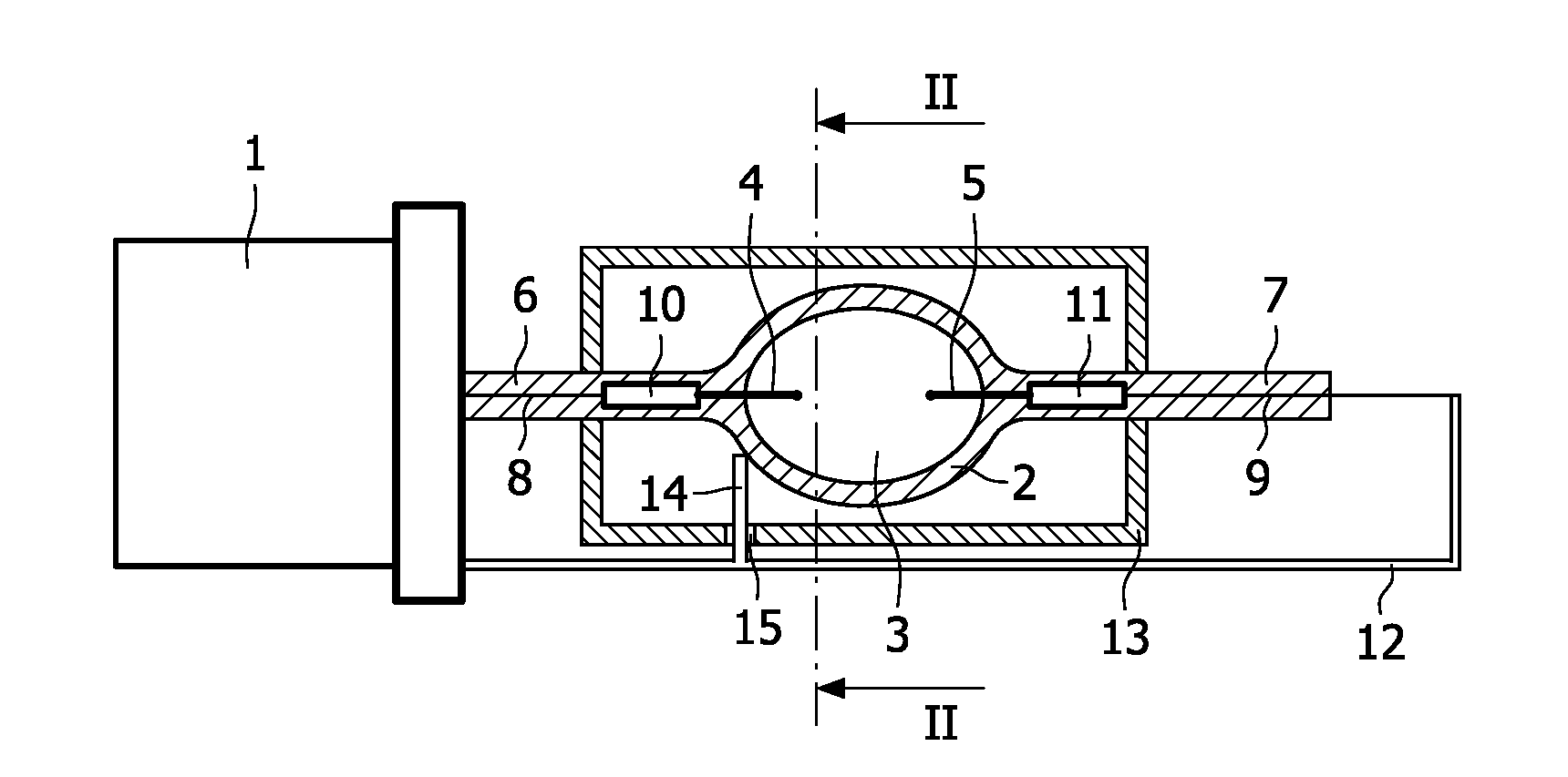
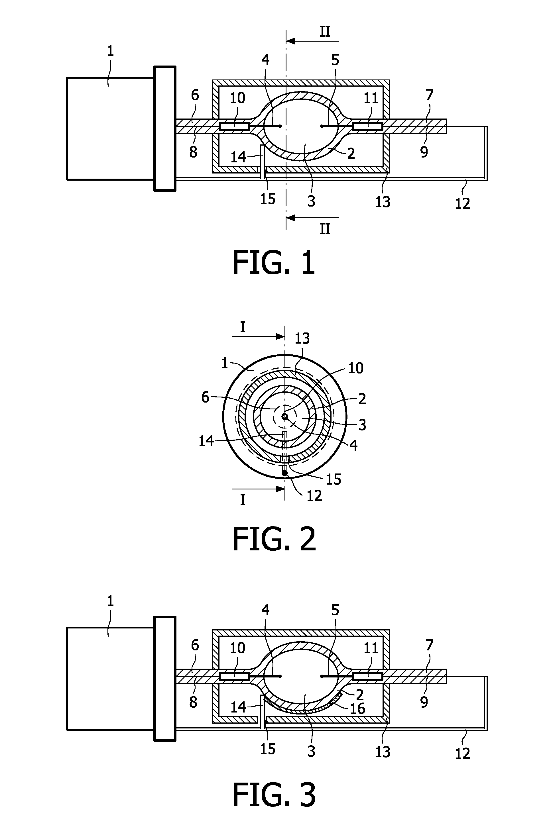
[0018]The first embodiment of the lamp is shown in FIGS. 1 and 2. The lamp has a base portion 1 of insulating material for fixing the lamp in a lamp holder, which base portion 1 is provided with electric contacts (not shown in the Figures) for connecting the lamp to corresponding electric power-supply contact means in the lamp holder. FIG. 1 shows the lamp in a sectional view, except for the base portion 1. The lamp further comprises an inner bulb 2 enclosing a discharge space 3 filled with an ionizable gas. Two electrodes 4, 5 are embedded in the transparent material of the inner bulb 2 and extend in the discharge space 3 from opposite sides. The inner bulb 2 has two end portions 6, 7 accommodating electric current-supply means. The current-supply means in each end portion 6, 7 comprise conductive wires 8, 9 and molybdenum foils 10, 11 connected to each other. The electrodes 4, 5 are connected to the molybdenum foils 10, 11, respectively.

[0019]Electric power is supplied from the ba...


PUM


Abstract

A high-pressure discharge lamp comprising an inner bulb (2) with a discharge space (3) containing an ionizable filling is described. Two electrodes (4,5) project from opposite sides into the discharge space (3). An outer bulb (13) surrounds the inner bulb (2) and a current-supply conductor (12) extends outside the outer bulb (13) for supplying an electric current to one of the two electrodes (5). A starter antenna (14) is connected to they current-supplyconductor (12). The starter antenna (14) passes through an opening (15) in the wall of the outer bulb (13) and extends towards the outer surface of the inner bulb (2).

Description

FIELD OF THE INVENTION[0001]The invention relates to a high-pressure discharge lamp comprising an inner bulb with a discharge space containing an ionizable filling, and a first electrode and a second electrode projecting from opposite sides into said discharge space, an outer bulb surrounding said inner bulb and a current-supply conductor extending outside said outer bulb for supplying an electric current to the second electrode.BACKGROUND OF THE INVENTION[0002]High-pressure discharge lamps of this type can be used for many applications, for example, as headlamps of automobiles. The inner bulb comprises the light source of the lamp and the outer bulb is made of a material that absorbs the ultraviolet radiation from the inner bulb. Such a high-pressure discharge lamp having an inner bulb and an outer bulb is disclosed in U.S. Pat. No. 5,736,811.[0003]In general, a high-pressure discharge lamp of this type has the drawback that it requires a relatively high drive voltage to start the ...

Claims


Application Information

Patent Timeline
Patent Type & Authority Applications(United States)
IPC IPC(8): H01J61/54
CPCH01J61/547H01J61/34
Inventor KESSELS, MARCUS JOZEF HENRICUS
Owner KONINKLIJKE PHILIPS ELECTRONICS NV
Why Eureka
Try Eureka