Method and apparatus for using a color indicator to display frequency or channel selection

a technology of color indicators and frequency selection, applied in the direction of color television details, television system details, television systems, etc., can solve the problem of no known prior art devices, and achieve the effect of expanding the dimension of experien

Inactive Publication Date: 2010-07-22
AERIELLE TECH
View PDF4 Cites 22 Cited by
  • Summary
  • Abstract
  • Description
  • Claims
  • Application Information

AI Technical Summary

Benefits of technology

[0008]The present invention is a method and apparatus for employing color display alone to indicate the currently tuned channel or frequency selected on any device. The various objects and advantages of the inventive method and apparatus are easily understood and appreciated when considering the inventive system as being integrated in an audio-sharing unit. An audio-sharing unit is a new type of consumer product that allows users to share compact disk (CD) quality audio in real time. The application of such a device involves the use of two or more identical audio-sharing units, each with its own RF transceiver. An audio-sharing unit, when in transmit mode, transmits an RF signal modulated with audio from the transmitting unit's source input (a music source, such as a CD or MP3 player). One or more other identical audio-sharing units (when in receive mode, and in range of the transmitting audio-sharing unit) receive and demodulate the transmitted signal. This allows two or more users to simultaneously listen to the same audio source. The transmitting user can also listen to the source through a local headphone jack.
[0015]Yet another object of the present invention is to provide a frequency / channel indicator that expands the dimensions of experience in using transmission media by invoking emotion and identity in connection with certain colors representing certain channels.

Problems solved by technology

Despite such customization schemes, there are no known prior art devices, or documents describing possible devices, in which there is shown a way for a user to tailor a device to display a selected color for indicating the frequency at which he or she is transmitting a signal.

Method used


Image

  • Method and apparatus for using a color indicator to display frequency or channel selection
  • Method and apparatus for using a color indicator to display frequency or channel selection
  • Method and apparatus for using a color indicator to display frequency or channel selection

Examples


Embodiment Construction

[0032]Referring to FIGS. 1 through 11, wherein like reference numerals refer to like components in the various views, there is illustrated therein a new and improved method and apparatus for using a color indicator for displaying a channel or frequency selection.

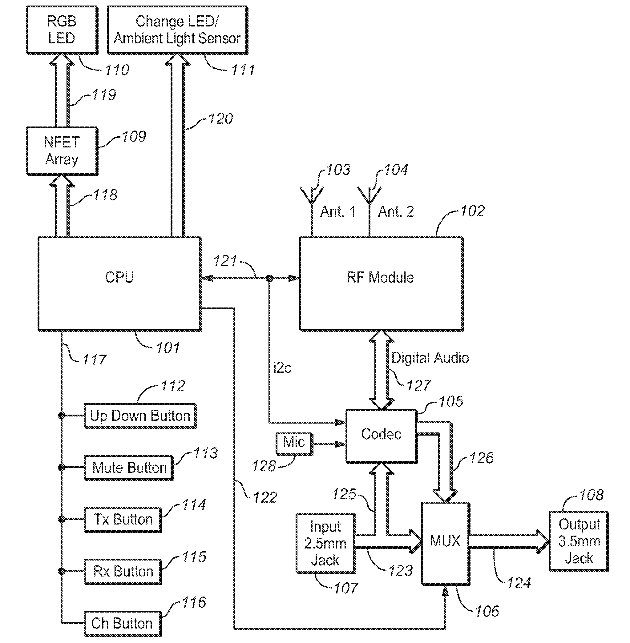
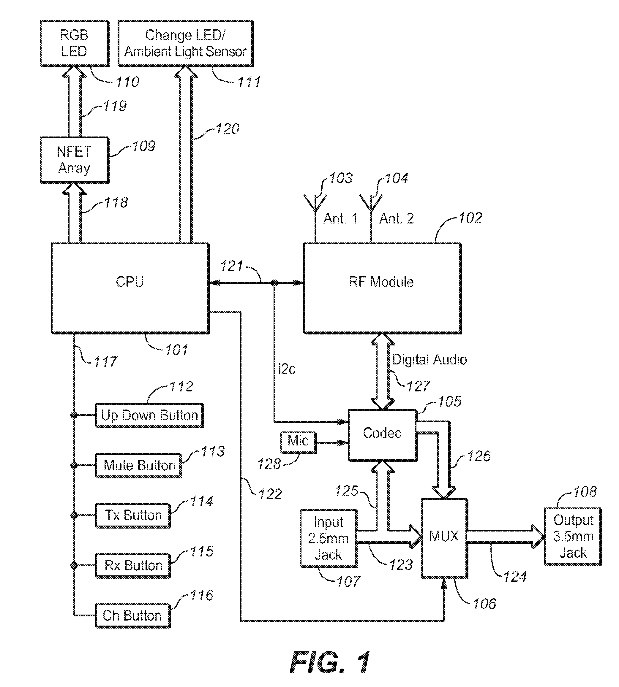
[0033]Turning first to FIGS. 1 through 6, there is shown an audio-sharing device for wired and / or wireless transfer of digital content and / or data between multimedia players, which consists of several interconnected subsystems. Such a device is an ideal implementation of the color display / frequency-indicating system of the present invention. In an exemplary audio-sharing unit, invented and designed by the present applicant, a central processing unit (CPU) CPU 101 controls the overall behavior of the audio-processing unit. CPU 101 is connected to N-channel FET array 109 via control bus 118. Control bus 118 is used by CPU 101 to control N-channel FET array 109, and thereby RGB LED assembly 110. RGB LED assembly 110 is connecte...


PUM


Abstract

A system for matching the currently tuned frequency of a signal transmitting device with that of a signal receiving device, including a transmitter having an illuminated color display which changes colors in relation to the channel or frequency on which the transmitter is currently tuned, and a signal receiving device having an illuminated color display which changes colors in relation to the channel or frequency on which the signal receiving unit is currently tuned. Each device has a channel selector function so that the frequency to which the device is tuned can be changed, thereby changing the color displayed.

Description

BACKGROUND OF THE INVENTION[0001]1. Technical Field[0002]The present invention relates most generally to consumer electronic devices, and more particularly to means for indicating channel or frequency selection, and still more particularly to a method and apparatus for using color as the exclusive means for indicating a channel or frequency in use on a multimedia playback device or other electronic device for transmitting audio and / or video files from a transmitting device to a receiving device.[0003]2. Background Art[0004]Typical transmitter and receiver devices allow a user to select a frequency on which to transmit or receive signals. An example would be a handheld walkie-talkie system, in which one can select one of a multitude of transmit or receive frequencies. Each frequency is indicated, for example, by a number from 0 to 9. Each of the frequency selections are actual hard coded transmit frequencies and are duplicated in the receiving unit. Thus, setting the transmitter and ...

Claims


Application Information

Patent Timeline
Patent Type & Authority Applications(United States)
IPC IPC(8): H04N5/50
CPCG01D7/005
Inventor HAGGIS, JOHN R.COHEN, MARTINCOHEN, ARTHUR L.LAU, FRANCIS
Owner AERIELLE TECH
Why Eureka
Try Eureka