Magnetic detector including magnetoresistive element and impact sensor

a technology of impact sensor and magnetic head, which is applied in the manufacture of flux-sensitive heads, instruments, and recording information storage, etc., can solve the problems of difficult to detect a collision of the magnetic head and the recording medium, the magnetic head may collide with and the protruding protruding head

Active Publication Date: 2010-07-22
TDK CORPARATION
View PDF7 Cites 18 Cited by
  • Summary
  • Abstract
  • Description
  • Claims
  • Application Information

AI Technical Summary

Benefits of technology

[0013]It is an object of the present invention to provide a magnetic detector, a thin-film magnetic head, a head assembly and a magnetic disk drive each of which includes a magnetoresistive element and an impact sensor and is capable of detecting an impact without affecting the characteristics of the magnetoresistive element.
[0022]In each of the magnetic detector, the thin-film magnetic head, the head assembly and the magnetic disk drive of the present invention, the impact sensor has a plurality of sensor-constituent layers that are made of materials the same as those of the plurality of element-constituent layers and stacked in an order the same as the plurality of element-constituent layers. The impact detecting layer of the impact sensor corresponding to the free layer of the magnetoresistive element exhibits a greater amount of change in magnetization direction when an impact is received, compared with the free layer. Consequently, according to the present invention, it is possible with the impact sensor to detect an impact without affecting the characteristics of the magnetoresistive element. Furthermore, according to the present invention, it is possible to form the impact sensor at the same time as the magnetoresistive element.

Problems solved by technology

In a magnetic disk drive, if there are protrusions on the surface of the recording medium caused by, for example, adhesion of foreign substances or defects of the recording medium, the magnetic head may collide with the protrusions.
It is difficult to perform proper reading and writing in portions of the recording medium with which the magnetic head collides.
However, for a magnetic head using an MR element having a low resistance-temperature coefficient such as a TMR element, it is difficult to detect a collision of the magnetic head with the recording medium through the above-described method.
However, this method has the following problem.
Therefore, the free layer having a magnetostriction constant having a large absolute value is undesirable for the characteristics of the MR element although it is desirable in detecting an impact on the magnetic head.
However, this requires a process dedicated to forming the sensor in the manufacture of the magnetic head and thereby makes the manufacturing process for the magnetic head more complicated.
As a result, even if the magnetic head suffers an impact, the magnetization direction of the magnetic layer of the fixed resistor corresponding to the free layer will not change easily.
It is therefore difficult with the fixed resistor of this magnetic detector to detect an impact on the magnetic head.

Method used


Image

  • Magnetic detector including magnetoresistive element and impact sensor
  • Magnetic detector including magnetoresistive element and impact sensor
  • Magnetic detector including magnetoresistive element and impact sensor

Examples


first embodiment

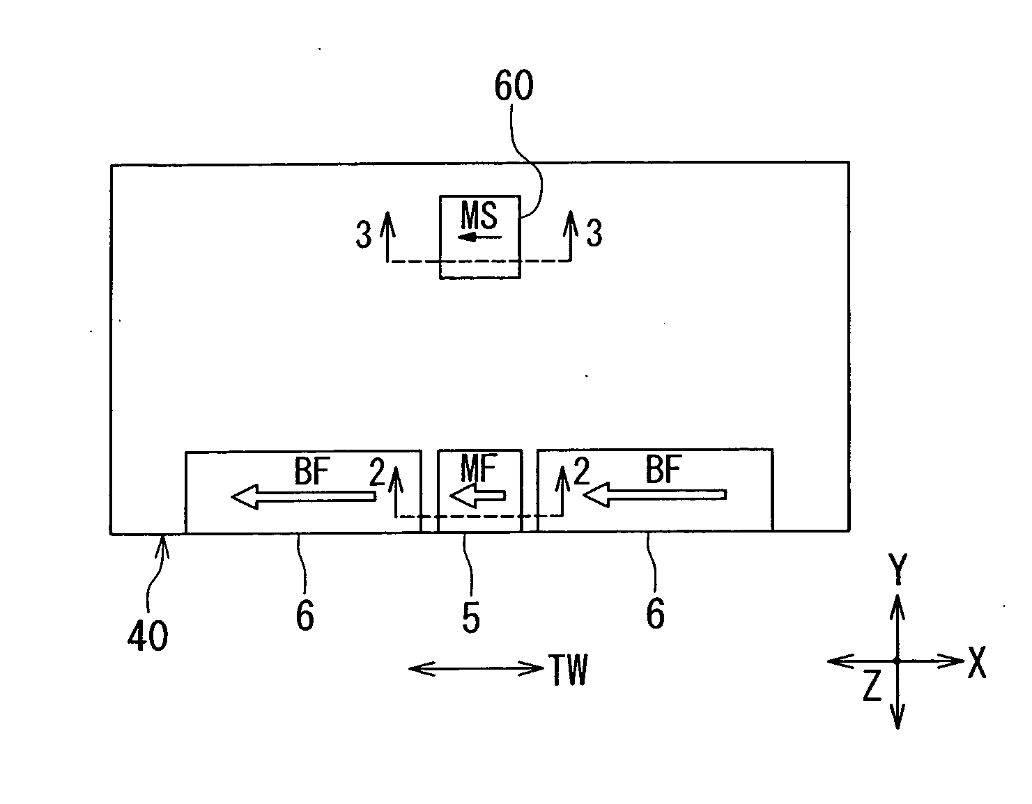
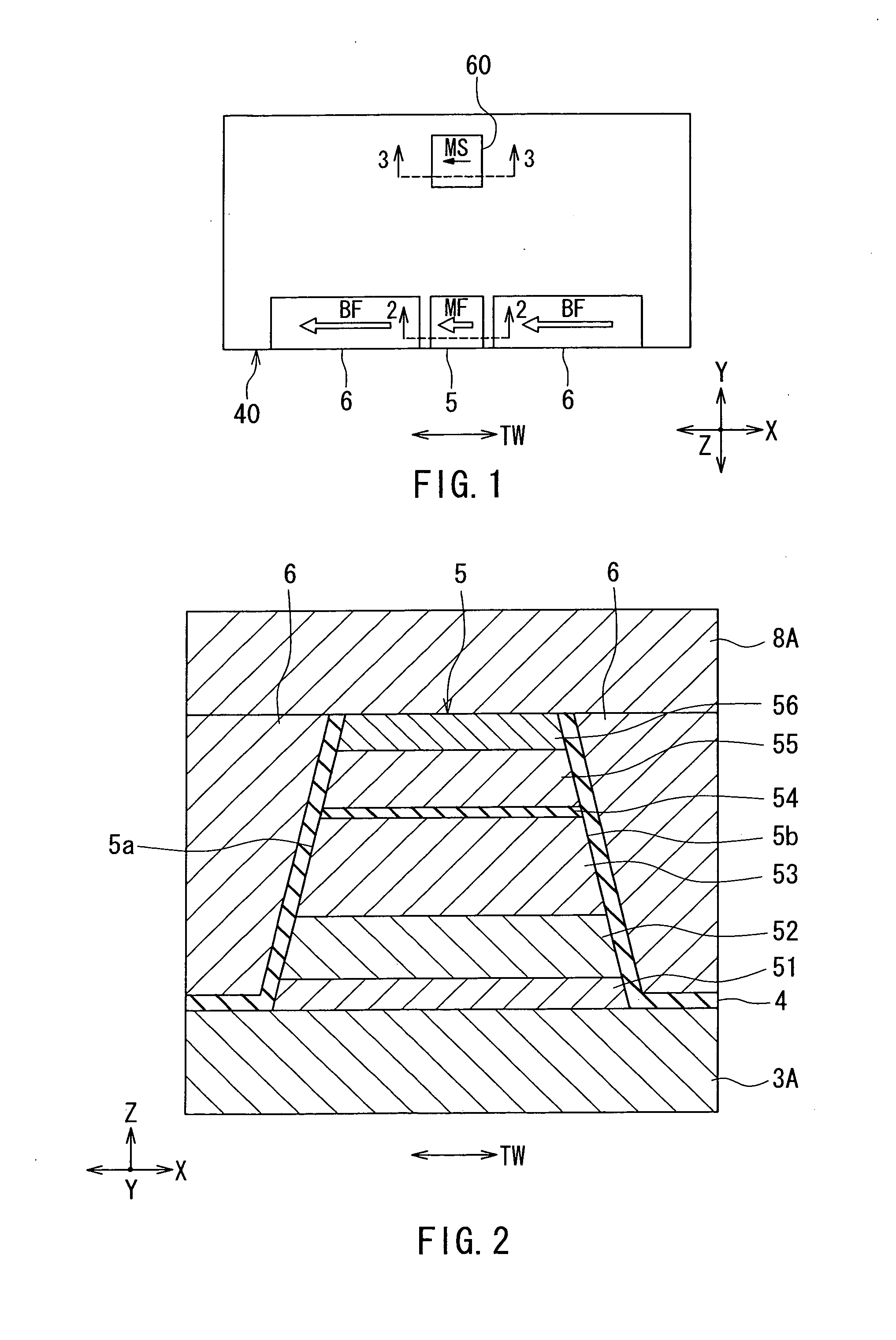
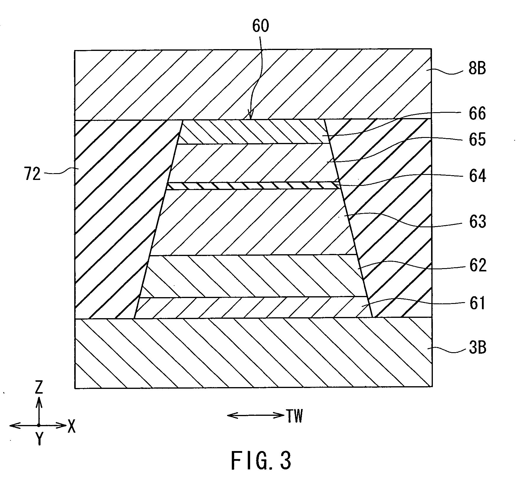
[0045]Embodiments of the present invention will now be described in detail with reference to the drawings. Reference is first made to FIG. 6 to describe a slider 210 including a thin-film magnetic head according to a first embodiment of the present invention. In a magnetic disk drive the slider 210 is placed to face toward a circular-plate-shaped recording medium (a magnetic disk platter) that is driven to rotate. In FIG. 6 the X direction is across the tracks of the recording medium, the Y direction is perpendicular to the surface of the recording medium, and the Z direction is the direction of travel of the recording medium as seen from the slider 210. The X, Y and Z directions are orthogonal to one another. The slider 210 has a base body 211. The base body 211 is nearly hexahedron-shaped. One of the six surfaces of the base body 211 is designed to face toward the surface of the recording medium. At this one of the six surfaces, there is formed a medium facing surface 40 to face t...

second embodiment

[0125]Reference is now made to FIG. 19 to describe a second embodiment of the present invention. FIG. 19 is a plan view showing a main part of a magnetic detector according to the second embodiment. In the second embodiment, as shown in FIG. 19, two bias magnetic field applying layers 6B for the sensor are provided on opposite sides of the impact sensor 60 in the track width direction, with insulating films (not shown) provided between the impact sensor 60 and the respective layers 6B. The bias magnetic field applying layers 6B for the sensor generate a bias magnetic field for the sensor in the track width direction. The magnetization direction of the impact detecting layer 65 in the initial state is directed to the track width direction by the bias magnetic field for the sensor. In FIG. 19 the arrows ‘BS’ indicate the direction of the bias magnetic field for the sensor generated by the bias magnetic field applying layers 6B for the sensor.

[0126]The bias magnetic field applying laye...

third embodiment

[0129]Reference is now made to FIG. 20 to describe a third embodiment of the present invention. FIG. 20 is a plan view showing a main part of a magnetic detector according to the third embodiment. In the third embodiment, as in the second embodiment, two bias magnetic field applying layers 6B for the sensor are provided on opposite sides of the impact sensor 60 in the track width direction with insulating films 4B provided between the impact sensor 60 and the respective layers 6B, as shown in FIG. 20. The bias magnetic field applying layers 6B for the sensor generate a bias magnetic field for the sensor in the track width direction. In the third embodiment the length of the bias magnetic field applying layers 6B for the sensor taken in the track width direction is equal to the length of the bias magnetic field applying layers 6 taken in the track width direction. The magnitude of the bias magnetic field for the sensor is equal to or nearly equal to the magnitude of the bias magnetic...


PUM

PropertyMeasurementUnit
distanceaaaaaaaaaa
distanceaaaaaaaaaa
magnetoresistiveaaaaaaaaaa

Abstract

A magnetic detector includes a magnetoresistive element and an impact sensor. The magnetoresistive element has a plurality of element-constituent layers that are stacked and include a free layer having a magnetization direction that changes in response to a magnetic field to be detected by the magnetic detector. The impact sensor has a plurality of sensor-constituent layers that are made of materials the same as those of the element-constituent layers and stacked in the same order as the element-constituent layers. The plurality of sensor-constituent layers include an impact detecting layer corresponding to the free layer and having a magnetization direction that changes by an inverse magnetostrictive effect in response to distortion created in the impact detecting layer by an impact received by the magnetic detector. The impact detecting layer exhibits a greater amount of change in magnetization direction when the magnetic detector receives an impact, compared with the free layer.

Description

BACKGROUND OF THE INVENTION[0001]1. Field of the Invention[0002]The present invention relates to a magnetic detector, a thin-film magnetic head, a head assembly and a magnetic disk drive each of which includes a magnetoresistive element and an impact sensor.[0003]2. Description of the Related Art[0004]A magnetic disk drive includes a recording medium to be driven to rotate, and a thin-film magnetic head for writing data on and reading data from the recording medium. The thin-film magnetic head for use in the magnetic disk drive is typically in the form of a slider with a thin-film magnetic head element (hereinafter, also simply referred to as a head element) provided at a rear end thereof. In the magnetic disk drive the slider is flexibly supported by a suspension so as to face toward the recording medium. In the magnetic disk drive, when the recording medium rotates, an airflow passes between the recording medium and the slider and causes a lift to be exerted on the slider. This li...

Claims


Application Information

Patent Timeline
Patent Type & Authority Applications(United States)
IPC IPC(8): G11B5/127G01R33/02
CPCB82Y25/00G01R33/093G11B5/3932G11B5/40
Inventor YANAGISAWA, TAKUMI
Owner TDK CORPARATION
Why Eureka
Try Eureka