Sense amplifier with a compensating circuit
- Summary
- Abstract
- Description
- Claims
- Application Information
AI Technical Summary
Problems solved by technology
Method used
Image


Examples
Embodiment Construction
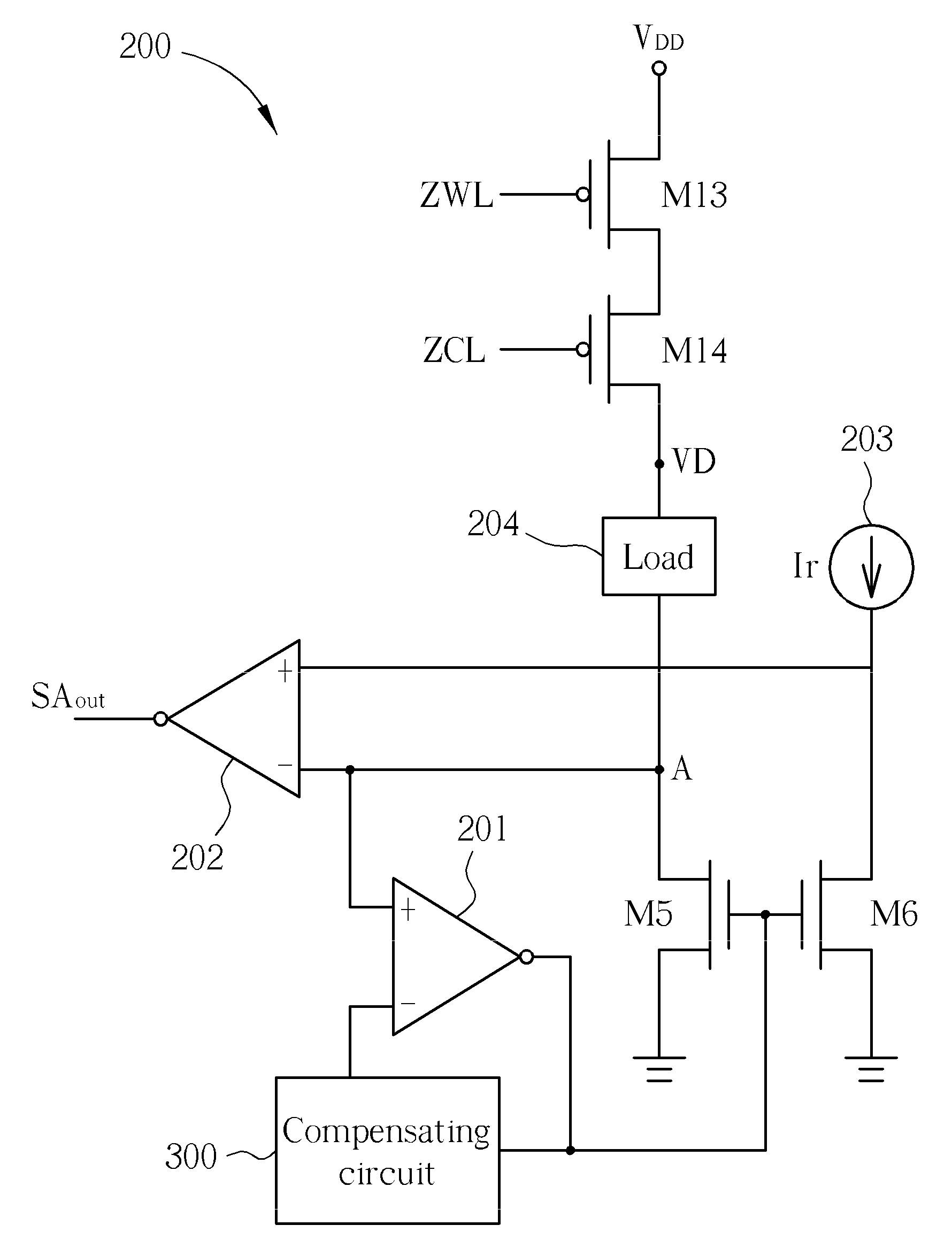
[0014]Please refer to FIG. 2. FIG. 2 is a diagram illustrating a sense amplifier 200 for a memory according to the present invention. The sense amplifier 200 comprises an operational amplifier 201, a comparator 202, a reference current source 203, a compensating circuit 300, and four transistors M5, M6, M13, and M14. The transistors M5 and M6 are NMOS transistors. The transistors M13 and M14 are controlled by word lines ZWL and ZCL of the memory. The transistors M13 and M14 are PMOS transistors. The drain of the transistor M5 is coupled to a bit line of the memory. The gate of the transistor M5 is coupled to the compensating circuit 300. The source of the transistor M5 is coupled to the ground. The transistor M5 and the operational amplifier 201 form a negative feedback loop so as to increase the stability of the sense amplifier 200. The positive input end of the comparator 202 is coupled to the reference current source 203. The negative input end of the comparator 202 is coupled to...
PUM
 Abstract
Description
Claims
Application Information