Fiber cutting mechanism and laser light source application apparatus comprising the mechanism

a technology of laser light source and fiber cutting mechanism, which is applied in the direction of fibre light guides, instruments, manufacturing tools, etc., can solve the problems of high difficulty level in the realization of a light source for green or blue by a semiconductor laser or the like, removal of laser light source incorporated in the laser light source application apparatus, etc., and achieve the effect of preventing secondary utilization of a fiber laser resonator alone and secondary utilization of a fiber laser light source incorporated in the device tha

Inactive Publication Date: 2010-07-22
PANASONIC CORP
View PDF7 Cites 14 Cited by
  • Summary
  • Abstract
  • Description
  • Claims
  • Application Information

AI Technical Summary

Benefits of technology

[0018]According to the present invention, secondary utilization of a fiber laser light source incorporated in a device that uses a laser light can be prevented. Additionally, secondary utilization of a fiber laser resonator alone can be prevented.

Problems solved by technology

However, realization of a light source for green or blue by a semiconductor laser or the like is difficult, and a compact light source with high productivity is sought after.
Particularly, the difficulty level in the realization of a light source for green is high, since there is no appropriate material for forming a semiconductor laser for obtaining a green output light.
Therefore, there is a problem that the laser light source incorporated in a laser light source application apparatus is removed for secondary utilization in other usages unforeseen by the designer.

Method used


Image

  • Fiber cutting mechanism and laser light source application apparatus comprising the mechanism
  • Fiber cutting mechanism and laser light source application apparatus comprising the mechanism
  • Fiber cutting mechanism and laser light source application apparatus comprising the mechanism

Examples


first embodiment

The First Embodiment

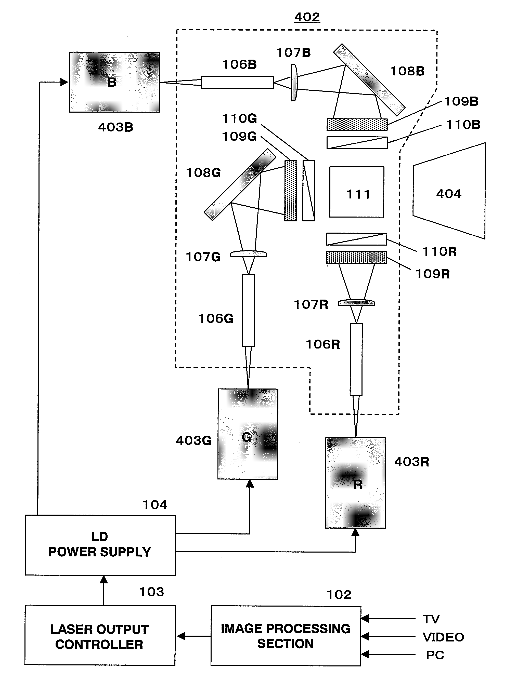
[0103]FIG. 7A and FIG. 7B are diagrams showing a structure of a fiber cutting mechanism according to the first embodiment of the present invention. The fiber cutting mechanism according to the first embodiment comprises: a fiber cutting section 1102, a power supply 1103, a connection determining section 1104, a switch 1106, and fiber holders 1010, which are provided on the green laser light source 403G side; and a control circuit 1108 and a power supply 1109, which are provided on the optical engine 402 side. The connection determining section 1104 and the control circuit 1108 are electrically connected via a connector 1105. A lithium battery or the like with long battery life is used as the power supply 1103 and 1109.

[0104]The fiber cutting section 1102 has a box structure that is: a case 1003 provided with, a heater 1006, a chemical agent 1005 deposited therein and sealed in with a cover 1004. The cover 1004 is provided with at least one groove 1011. The heater...

second embodiment

The Second Embodiment

[0107]FIG. 8A and FIG. 8B are diagrams showing a structure of a fiber cutting mechanism according to the second embodiment of the present invention. The fiber cutting mechanism according to the second embodiment comprises: a guide blade 603, a slit 604, and fiber holders 605, which are provided on the green laser light source 403G side; and a fixture 602 provided on the optical engine 402 side.

[0108]At the green laser light source 403G, a fiber 601 is fixed onto the fiber holders 605 such that the above described cutting position area is disposed at the slit 604. This slit 604 is formed in a shape that can have the fixture 602 inserted therein. In between the fiber holders 605, the guide blade 603 is provided in a position that contacts the fiber 601. The fixture 602 is capable of rotating around a rotational axis provided on the optical engine 402, and has a lock pin 608.

[0109]The green laser light source 403G is fixed onto the optical engine 402 with the fixtu...

third embodiment

The Third Embodiment

[0111]FIG. 9A and FIG. 9B are diagrams showing a structure of a fiber cutting mechanism according to the third embodiment of the present invention. The fiber cutting mechanism according to the third embodiment comprises: a guide blade 703, a slit 704, and fiber holders 705, which are provided on the green laser light source 403G side; and a fixture 702 provided on the optical engine 402 side.

[0112]At the green laser light source 403G, a fiber 701 is fixed onto the fiber holders 705 such that the above described cutting position area is disposed at the slit 704. This slit 704 is formed in a shape that can have the fixture 702 inserted therein. In between the fiber holders 705, the guide blade 703 is provided in a position that contacts the fiber 701. The fixture 702 has a shape like an arrowhead with a barb.

[0113]The green laser light source 403G is fixed onto the optical engine 702 with the fixture 702 by the following procedure. The fixture 702 in an initial sta...


PUM

PropertyMeasurementUnit
wavelengthaaaaaaaaaa
outer diameteraaaaaaaaaa
lengthaaaaaaaaaa

Abstract

Provided is a fiber cutting mechanism that prevents secondary utilization of a fiber laser light source incorporated in a device that uses a laser light. With a characteristic fiber cutting mechanism, when a laser device is separated from a laser light source application apparatus, at least a fiber 26 is cut in an specific area from a point within a fiber grating 29 to a connection point between the fiber grating 29 and the fiber 26 containing a laser activating substance (cutting position area (1)).

Description

TECHNICAL FIELD[0001]The present invention relates to a fiber cutting mechanism incorporated in a laser device which obtains a stable high-power visible laser by combining a fiber laser and a wavelength conversion element, and to a laser light source application apparatus comprising the fiber cutting mechanism.BACKGROUND ART[0002]A visible light source capable of a watt-class high output with strong monochromaticity is considered to be necessary in order for the realization of a large display, a high brightness display or the like. Among the three primary colors, red, green and blue, as a light source for red, a red high output semiconductor laser is applicable, which is a compact light source with high productivity used in a DVD recorder or the like. However, realization of a light source for green or blue by a semiconductor laser or the like is difficult, and a compact light source with high productivity is sought after. Particularly, the difficulty level in the realization of a l...

Claims


Application Information

Patent Timeline
Patent Type & Authority Applications(United States)
IPC IPC(8): H01S3/02G02B6/00
CPCG02B6/0008G02B6/0028G02B6/25H01S3/0014H01S3/0064H01S3/0092H04N9/3161H01S3/08054H01S3/094015H01S3/09415H01S3/10H01S3/1055H01S3/0675
Inventor FURUYA, HIROYUKIYAMAMOTO, KAZUHISAKADOWAKI, SHINICHI
Owner PANASONIC CORP
Why Eureka
Try Eureka