Two-ring optical buffer

a buffer and optical technology, applied in the field of two-ring optical buffers, can solve the problems of large delay, severe signal distortion, and the crow with n=100 only achieved undistorted buffering for one bi

Inactive Publication Date: 2010-07-22
NANYANG TECH UNIV
View PDF2 Cites 14 Cited by
  • Summary
  • Abstract
  • Description
  • Claims
  • Application Information

AI Technical Summary

Benefits of technology

[0007]For the first exemplary aspect a ratio of resonance splitting over resonance broadening may be approximately 0.6. A coupling length of the firs

Problems solved by technology

This method is interesting because it is a relatively simple configuration that can produce a large delay.
However, causality dictates that there is a constant delay-bandwidth product determined by the physical mechanism underlying the delay.
However, experimentally a CROW with N=100 has only achieved undistorted buffering for one bit.
This is because while the delay is i

Method used


Image

  • Two-ring optical buffer
  • Two-ring optical buffer
  • Two-ring optical buffer

Examples


Embodiment Construction

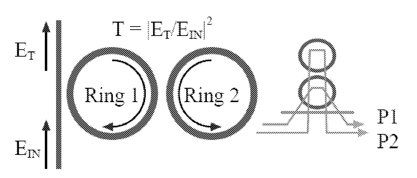
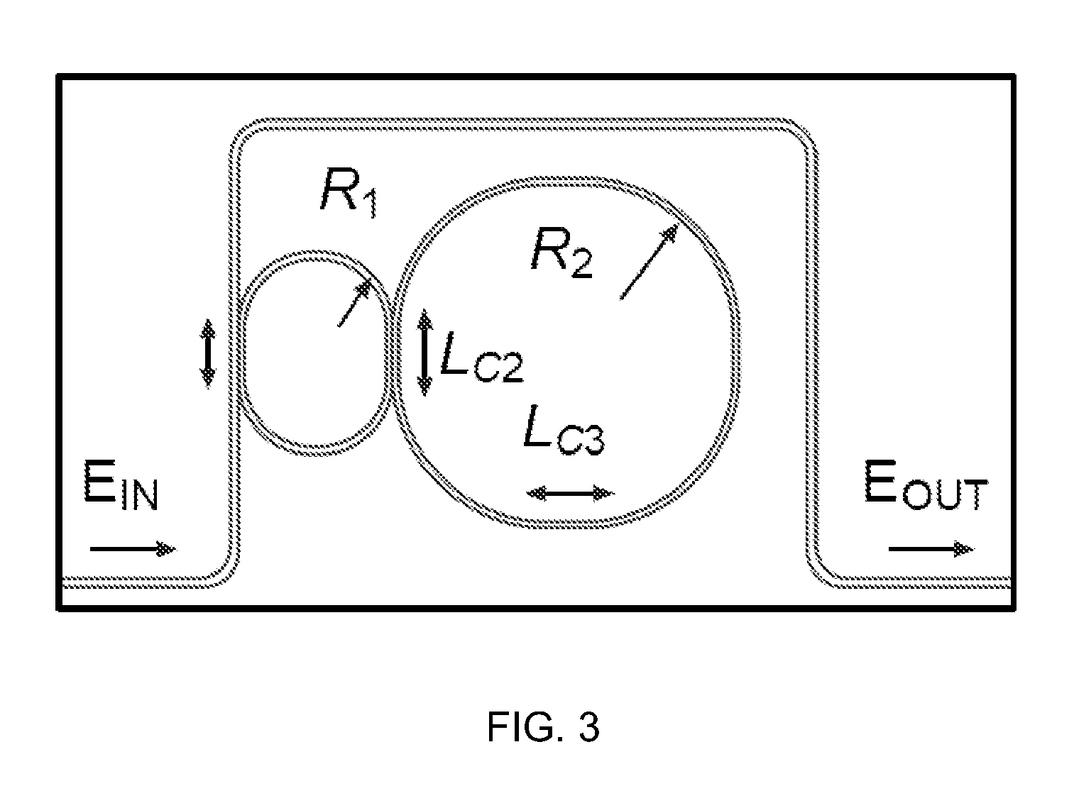
[0021]FIG. 1 shows a schematic representation of a two-ring, one-waveguide buffer with two mutually coupled rings being a first ring R1 and a second ring R2. First ring R1 is coupled to the waveguide bus and the second ring R2 is only coupled to the first ring R1. The second ring R2 is not coupled to a waveguide. The excited optical pathways are shown in the right inset.

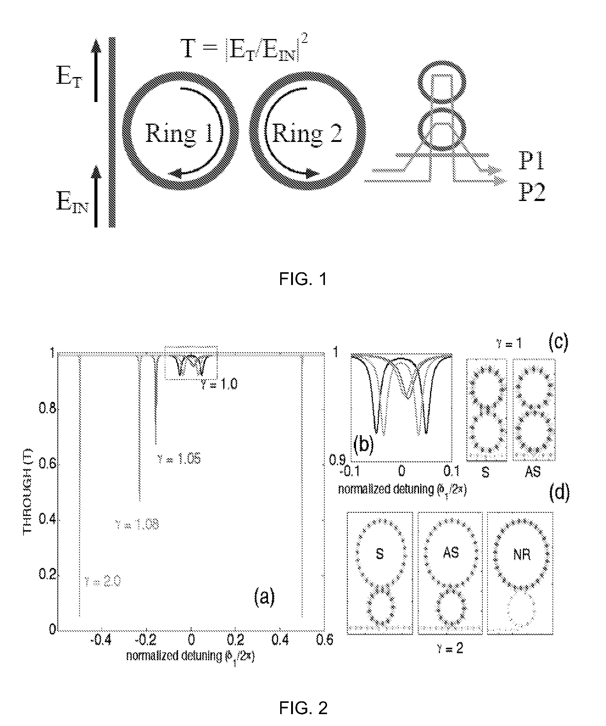
[0022]The optical buffer of FIGS. 1 and 3 has a ratio (γ), of the circumferential length of the second ring R2 to the first ring R1 of γ=2m, where m is an integer. Also, the ratio of the resonance splitting over the resonance broadening (Ω / Γ) should be approximately 0.6. That is, Ω / Γ˜0.6. Furthermore, the buffer should work in the strong coupling region. The splitting (Ω) is controlled by the coupling between the two rings R1 and R2. The broadening (Γ) is controlled by the coupling of the first ring R1 to the waveguide. Hence, there is an independent control of both parameters (Ω and Γ). Each of the splitting and the...


PUM


Abstract

A two-ring optical buffer comprising a first ring operatively connected to a waveguide and a second ring, the second ring being operatively connected to only the first ring, the second ring and the first ring having a circumferential ratio substantially equal to 2m, where m is an integer. A ratio of resonance splitting over resonance broadening may be approximately 0.6.

Description

TECHNICAL FIELD[0001]This invention relates to a two-ring optical buffer and refers particularly, though not exclusively, to a two-ring optical buffer where the first ring is operatively connected to a waveguide and the second ring, and the second ring is operatively connected to only the first ring, the second ring and the first ring having a circumferential ratio substantially equal to 2m, where m is an integer.BACKGROUND[0002]An optical buffer stores and holds an optical data stream for a fixed duration without conversion to electrical format, an important role in all-optical information processing. In order to perform buffering on chip in a small footprint, a great reduction in group velocity is necessary. Slow light schemes have been proposed using both optical and electronic resonances. Optically, the forward propagation of light is delayed by circulating it through many round trips in a resonator, which may be in the form of a ring resonator or as a defect mode in photonic cr...

Claims


Application Information

Patent Timeline
IPC IPC(8): G02B6/26
CPCG02B6/12007G02B6/29343
Inventor TOBING, LANDOBASA YOSEF MARIO A. L.MEI, TINGONG, OOI KWEN
Owner NANYANG TECH UNIV
Why Eureka
Try Eureka