Gas Booster System and Related Method

a booster system and gas technology, applied in the field of fluid systems, can solve the problems of reducing the service life affecting the reliability of the booster system, and the inability to adapt to multiple power sources, so as to improve the electrical improve the safety of the booster system, and facilitate maintenance, repair and inspection.

Active Publication Date: 2010-07-22
ETTER ENG
View PDF25 Cites 5 Cited by
  • Summary
  • Abstract
  • Description
  • Claims
  • Application Information

AI Technical Summary

Benefits of technology

[0013]In accordance with another aspect of the present invention, the tank assembly is hermetically sealed with respect to the ambient atmosphere. In a currently preferred embodiment, the ends of the substantially cylindrical drum casing are flange-sealed, and releasably mounted to the base and the scroll housing by threaded connections or other suitable fastening means (such as, for example, adhesives, clips, etc.) to form the hermetically sealed tank assembly. In one such embodiment, fluid enters the tank assembly through at least one inlet associated with the base, and exits through at least one outlet associated with the scroll housing. In another such embodiment, utility and service connections may penetrate the tank assembly and be provided to the motor in a manner that maintains the tank assembly in a hermetically sealed condition. In yet another such embodiment, a plurality of utility and service connections provided to the motor enable electrical power of different voltages or frequencies to be used in powering the motor during operation.
[0015]In accordance with another aspect of the present invention, the gas booster further comprises a sled assembly, which may be associated with the base and positioned beneath the tank assembly. In a currently preferred embodiment, when the hollow drum casing is disconnected from the base for any reason, the sled assembly may provide structural support and positional alignment to the hollow drum casing, and enable the hollow drum casing to be reconnected to the base quickly and easily.
[0017]One advantage of the gas booster system and method of the present invention is that aligning the motor and fan wheel within the hermetically-sealed tank assembly and along the axis of the hollow drum casing permits the motor to be cooled by the flow of fluid through the booster, thereby convectively transferring heat generated by the operating motor to the flowing fluid. Because the motor is positioned inside the tank assembly, and within the fluid flow path, the motor may be cooled by the flowing fluid, and pressure losses may be eliminated. Another advantage of the gas booster system and method of the present invention is that the versatile electrical feedthrough connection permits the motor to be powered from a variety of power sources. Because proper and sufficient electrical power may be provided through a single feedthrough connector, the booster may be installed into a variety of fluid systems without requiring a manual reconfiguration of the electrical connections within the tank assembly, thereby maintaining the hermetic seal of the tank assembly and improving the electrical safety of the booster system. Still another advantage of the gas booster system and method of the present invention is that the discharge piping may be oriented in any number of positions with respect to the tank assembly, which permits the booster system and method to be installed and used in fluid systems located in confined spaces, without requiring significant renovation of the surrounding area or realignment of the fluid system piping. Finally, another advantage of the gas booster system and method of the present invention is that the tank assembly may be readily opened for maintenance, repair, inspections or any other reason, and also restored to service, more quickly and easily than booster systems of the prior art.

Problems solved by technology

Also, gas boosters may be applied to systems in remote regions which may not have sufficient pressure due to pipe losses or leaks, or for other reasons.
Despite the aforementioned advantages associated with the use of gas boosters, there are a number of physical and operational limitations which hinder the widespread use of prior art systems and methods in piped fluid systems in general, and in natural gas or propane applications in particular.
While some gas boosters feature motors that are positioned within the path of the flowing fluid, thereby removing heat from the motor by convective heat transfer, such boosters may not be readily adapted for use with multiple sources of power, and must be manually reconfigured or adjusted to accommodate electric power at different voltage levels or frequencies.
Moreover, in gas boosters of the prior art, the alignment of the discharge outlet piping is typically limited to one or a small number of standard positions, and may not be readily adjusted in the field to accommodate varying system configurations or operating conditions.
This limitation tends to reduce the functionality of a typical gas booster, and also complicates its physical installation into piped fluid systems.

Method used


Image

  • Gas Booster System and Related Method
  • Gas Booster System and Related Method
  • Gas Booster System and Related Method

Examples


Embodiment Construction

[0028]The subject disclosure and present invention relate to improved systems and methods for increasing the pressure of piped fluids. As will be readily appreciated by those skilled in the pertinent art, the systems and methods disclosed herein are particularly applicable in natural gas or propane systems, but may be utilized or employed in many applications to increase the pressure of a variety of piped fluids. The advantages and other features of the systems and methods disclosed herein will become more readily apparent from the following detailed description of certain currently preferred embodiments of the invention taken in conjunction with the drawings, which set forth representative embodiments of the present disclosure.

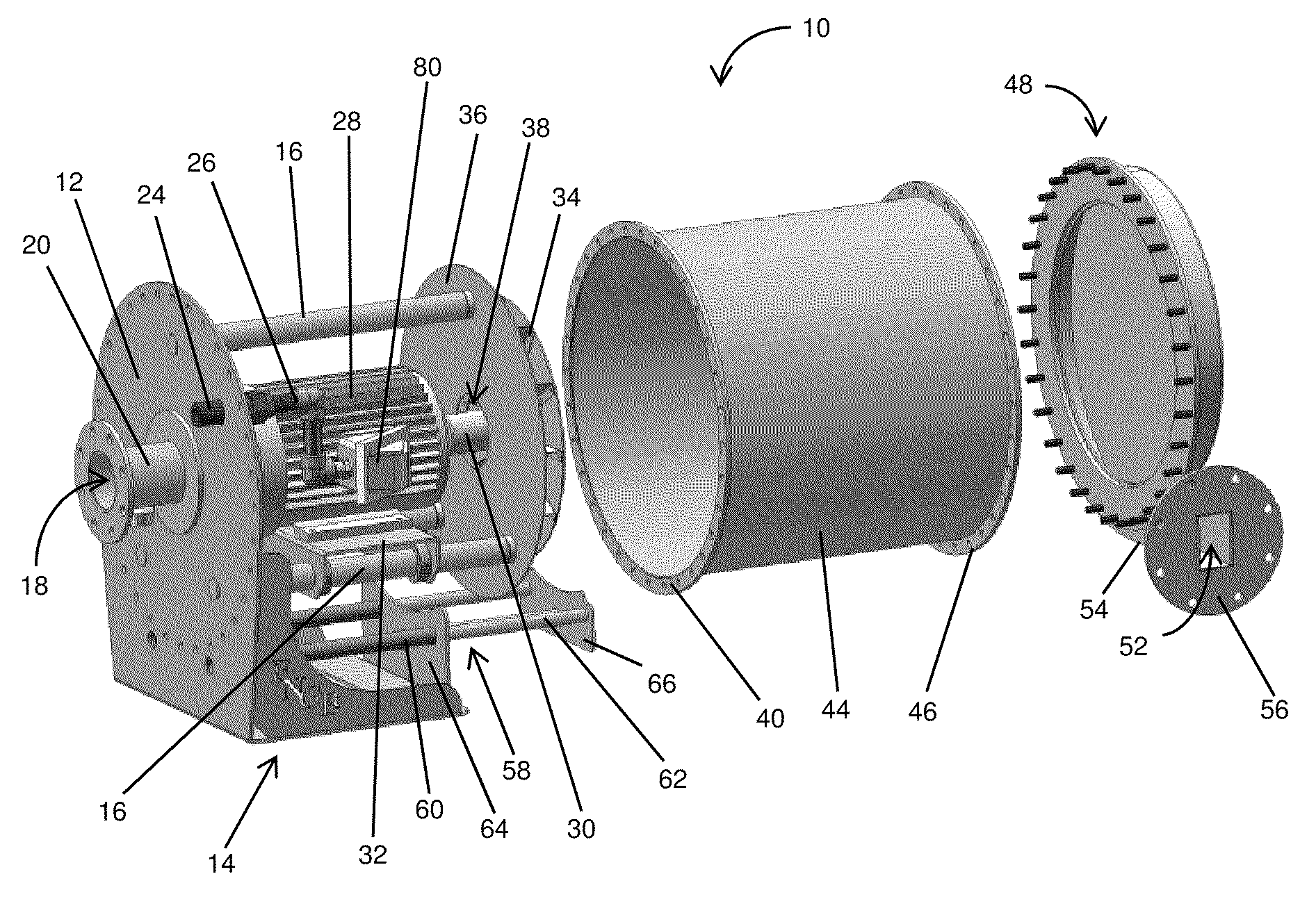
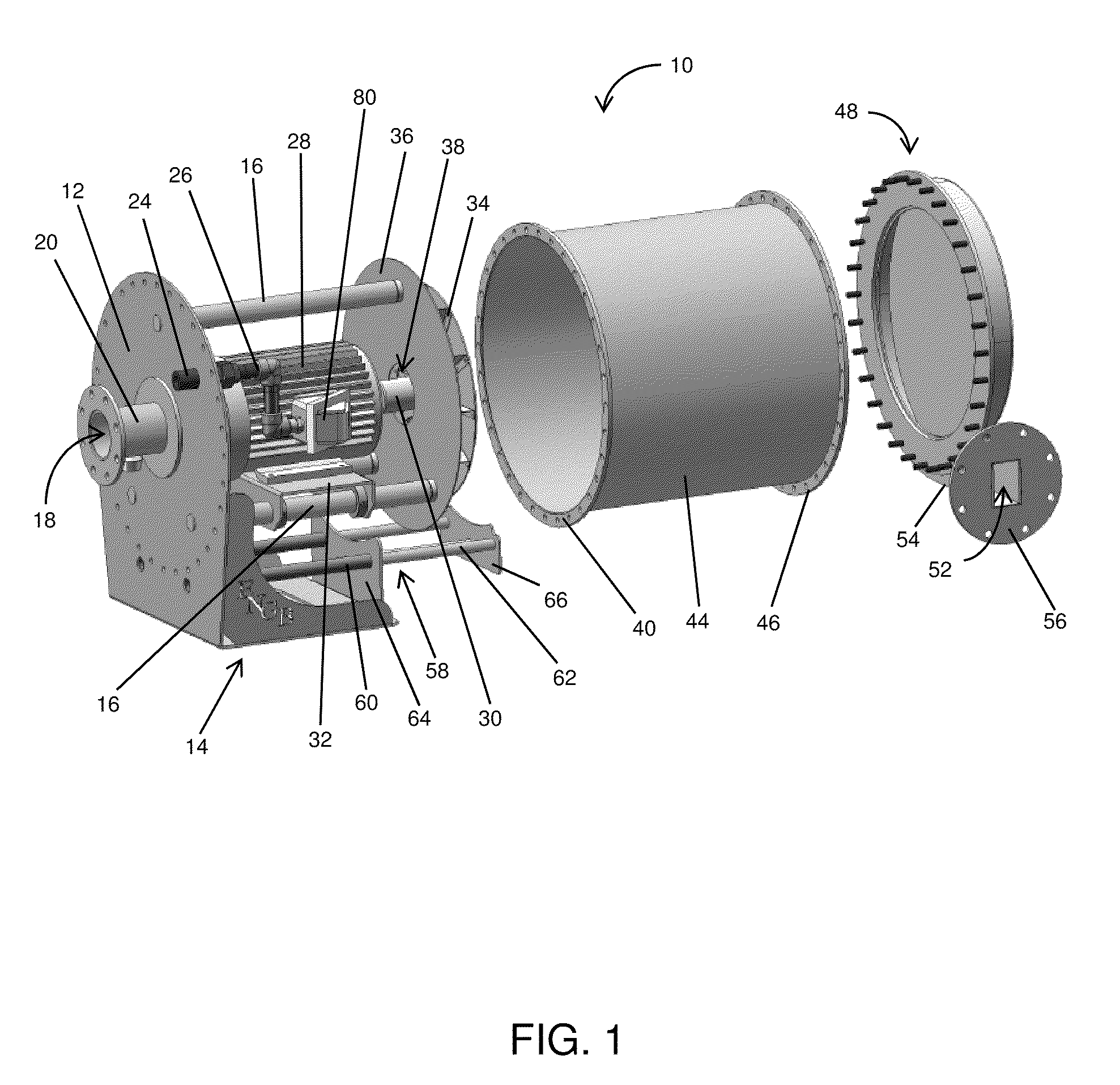
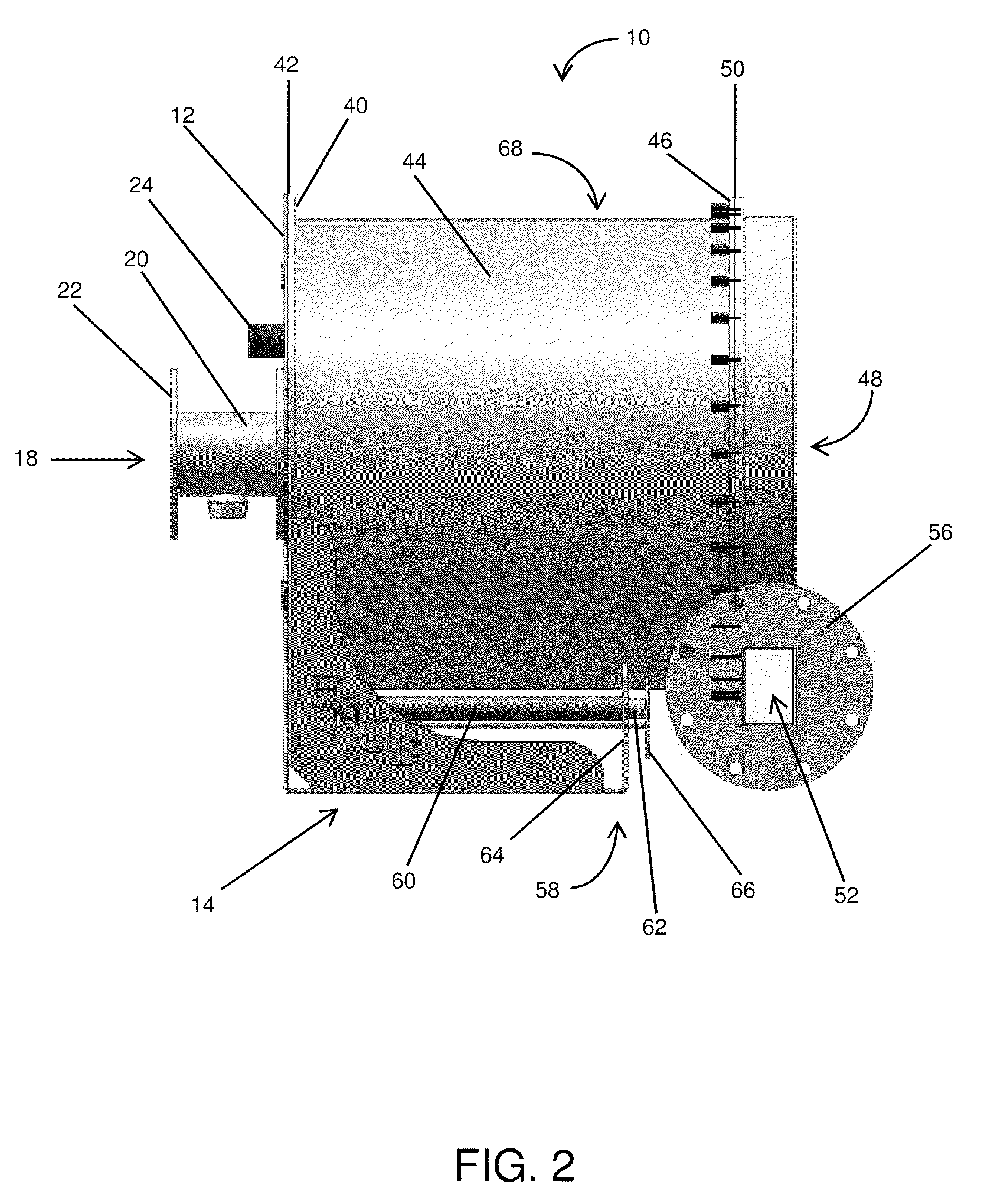
[0029]In FIGS. 1, 2, 3A, 3B and 4, an embodiment of a gas booster of the present invention is indicated generally by the numeral 10. Gas booster 10 comprises base 12, motor 28, fan wheel 34, drum 44, baffle plate 36, scroll housing 48, and sled assembly 58. M...


PUM


Abstract

An improved booster for use in piped fluid systems includes a motor, a fan wheel and a hermetically sealed tank assembly. Fluids enter the tank assembly through an inlet and are compressed within the tank assembly by a rotating fan wheel, before leaving the tank assembly through an outlet, which may be aligned in a plurality of angular configurations. The motor is powered by a versatile electrical connection which enters the tank assembly through a connector that maintains the hermetically sealed condition in the tank assembly, and can accommodate power of any voltage or frequency. The incremental pressure gain provided by the booster may be controlled by modifying the speed of the rotating fan wheel, and a sled assembly provides structural support and positional alignment for portions of the tank assembly when the booster system is opened for access.

Description

CROSS-REFERENCE TO RELATED APPLICATIONS[0001]This application claims the benefit of and priority to U.S. Patent Application No. 61 / 145,410, filed Jan. 16, 2009, the content of which is incorporated herein by reference in its entirety.BACKGROUND OF THE INVENTION[0002]1. Field of the Invention[0003]The present invention relates to fluid systems and, more particularly, to an improved system for increasing pressure in piped fluid systems, and related methods.[0004]2. Background of the Related Art[0005]In piped fluid systems, pumps or similar machines are sometimes used to elevate the pressure of the fluid, in order to overcome supply pressure deficiencies or pipe losses, to satisfy equipment pressure requirements (particularly in modern, low-emission or high-efficiency equipment), or for any other desired reason. Commonly called “boosters,” such systems and related methods perform mechanical work on fluid received at the inlet, thereby increasing the pressure of the fluid discharged at ...

Claims


Application Information

Patent Timeline
Patent Type & Authority Applications(United States)
IPC IPC(8): F04D25/06F04D29/40F04D29/58F04D29/60
CPCF04D25/06F04D29/403F04D29/624F04D29/626
Inventor ETTER, THOMAS M.MOORE, JON G.HALE, PATRICK M.
Owner ETTER ENG
Why Eureka
Try Eureka