Wire Saw

Active Publication Date: 2010-07-29
ILLINOIS TOOL WORKS INC
View PDF22 Cites 69 Cited by
  • Summary
  • Abstract
  • Description
  • Claims
  • Application Information

AI Technical Summary

Benefits of technology

[0014]In another embodiment of the invention, a wire take-up is provided that allows enough slack within the length of wire to permit sufficient bending of the wire as it cuts to prevent wire snapping. The device further includes a detector, for detecting the degree of bending of the wire and a control responsive to the detector for controlling the feed rate in response to the bending of the wire.
[0015]A plurality of wheels on the bow engage the diamond embedded wire and retain the wire as it moves in a circular path to cut the length of pipe. One of the wheels is a drive wheel having an annular groove in its outer surface into which the cutting wire is received. The wheel includes a first annular side member and an opposing second annular side member each of which has circular outer circumferences and attach to opposite sides of a circular central body. The outer circumferences of the side members are spaced from each other leaving a groove between them for receiving the diamond embedded cutting wire. The first side member is retained to the remaining portio

Problems solved by technology

One problem that that has plagued machines adapted to cut submerged pipe is that the machines typically include a plurality of contact pads that contact the surface of the pipe, and a pair of moveable arms that compress the pipe against the contact pads.
It has been found, however, that frequently the grasping arms do not force the length of pipe equally against all the retaining pads such that the device is somewhat skewed relative to the pipe.
As a consequence of the skewed pipe, the machine may shake during the cutting process or realign itself against the pipe causing the cutting wire to snap.
The serpentine wire take-up significantly enlarges the size of t

Method used


Image

  • Wire Saw
  • Wire Saw
  • Wire Saw

Examples


Embodiment Construction

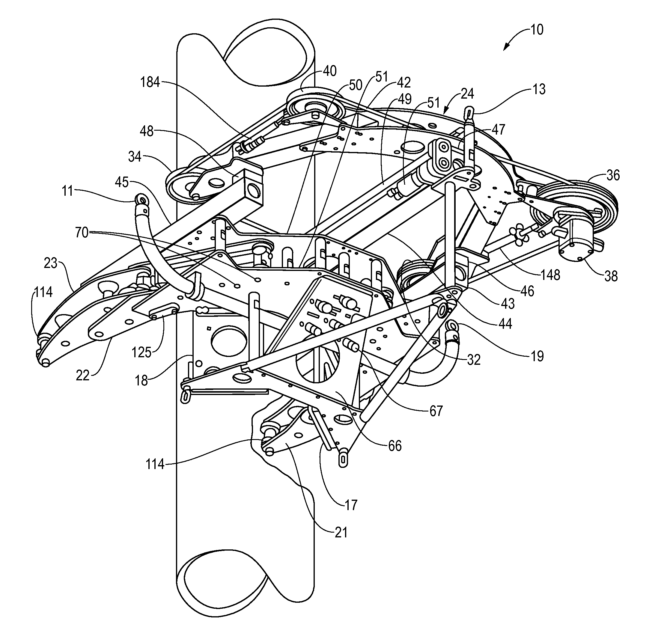
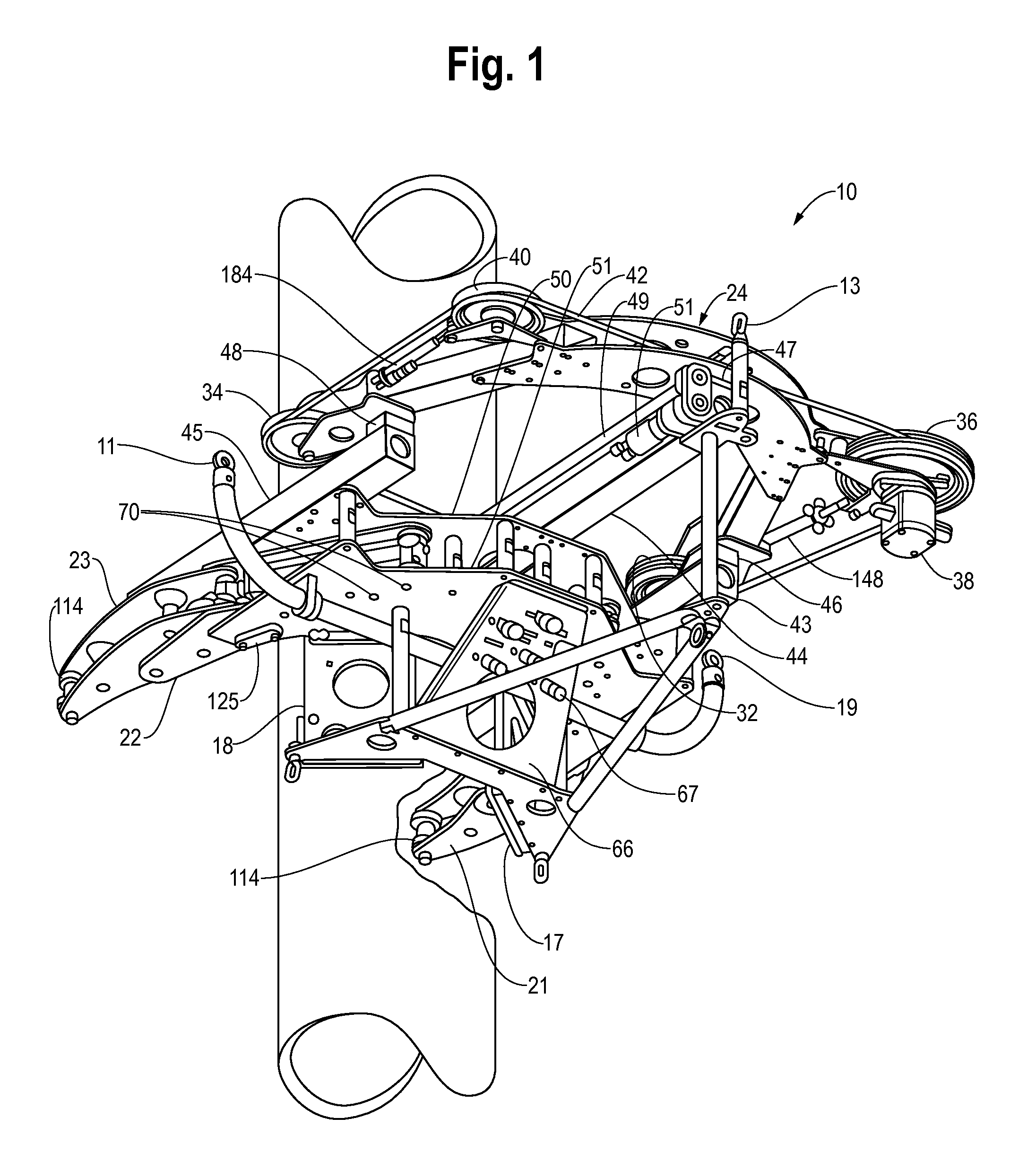
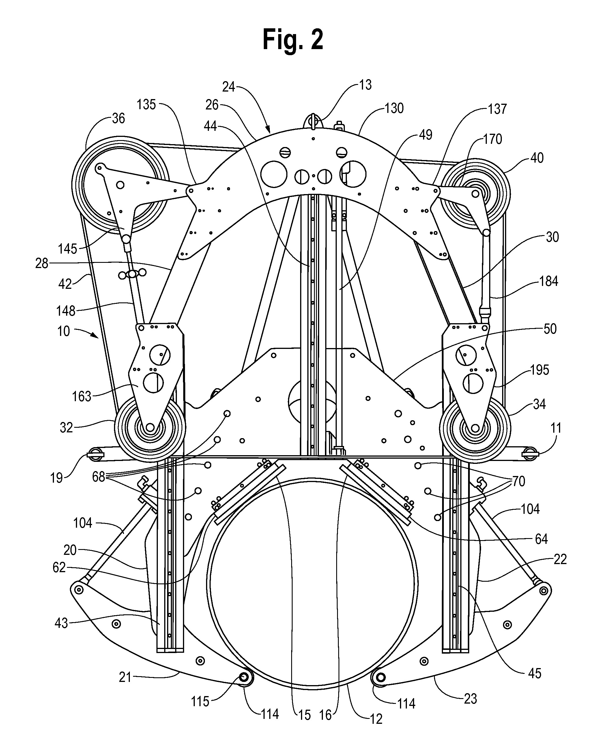
[0043]Referring to FIGS. 1 through 4, a wire cutting machine 10 for cutting a length of pipe 12 includes a frame 14 having a plurality of contact pads 15, 16, 17, 18 thereon for positioning the frame 14 against the surface of the pipe 12. The machine 10 is suspended at the desired elevation and orientation by a plurality of wires, not shown, that extend downward from the surface with each wire attaching to a connector 11, 13, 19 on the machine 10.

[0044]Mounted with respect to the frame 14 are first and second arm assemblies each of which includes an upper arm 20, 22 attached to the frame 14 and a lower arm 21, 23 movable with respect to the associated upper arms 20, 22 for reaching around the outer circumference of the pipe 12 and retain the frame 14 firmly against the pads 15-18. The machine 10 further includes a bow 24 having a central portion 26 and two generally arched arms 28, 30 having guide wheels 32, 34 at the distal ends thereof. Positioned near the central portion 26 is a ...


PUM

PropertyMeasurementUnit
Lengthaaaaaaaaaa
Forceaaaaaaaaaa
Diameteraaaaaaaaaa

Abstract

A device for cutting a length of pipe includes a clamp portion for clamping around a length of pipe and a bow moveable with respect to the clamp portion that retains a loop of diamond embedded wire. The device further includes a feed for driving the bow with respect to the clamp portion and a detector for detecting bending of the wire and a control responsive to the detector for controlling feed rates. The device is made of modular parts and has synchronizing arms for clamping around a length of pipe. In one embodiment, the wheels are retained in enclosures with slots through which the cutting wire passes.

Description

[0001]The applicant claims priority from his two provisional applications, the first filed Jan. 26, 2009 and assigned Ser. No. 61 / 147,163, and the second filed Mar. 18, 2009 and assigned Ser. No. 61 / 161,189. The present application relates to wire saws of the type used to cut pipe and in particular underwater pipe such as used to support offshore oil rigs and the like.BACKGROUND OF THE INVENTION[0002]Offshore oil rigs are supported by vertical pipes the lower ends of which are embedded in the ocean floor and the upper end of which extends above the surface. When an oil rig is abandoned, the supporting pipes must be sawed so as not to obstruct sea traffic or animal life.[0003]Metal pipe used to support underwater structures come in diameters from the very smallest available up to at least 72 inches. A machine suitable for cutting such pipe must be resistant to deterioration caused by salt water and must be sized to accept and machine the particular diameter of pipe to be cut. Present...

Claims


Application Information

Patent Timeline
IPC IPC(8): B26D5/00B27B13/00B26D7/02
CPCB23D57/0007Y10T83/68B23D57/0061B26D1/48B26D3/16B26D7/02B26D2007/013B23D57/0069B23D57/0084B23Q9/0042Y10T83/7487Y10T83/424Y10T83/141Y10T83/9292B23D59/001Y10T83/707B23D57/0053
Inventor PIERCE, KENNETH R.
Owner ILLINOIS TOOL WORKS INC
Why Eureka
Try Eureka