
Auto Igniting Smoking Pipe

Inactive Publication Date: 2010-07-29
JONES MIKE
View PDF0 Cites 9 Cited by
  • Summary
  • Abstract
  • Description
  • Claims
  • Application Information

AI Technical Summary

Benefits of technology

[0007]It is an object of the herein described invention to provide a compact, easy-to-use pipe for smoking combustible substances, such as tobacco.
[0010]These and other objects of the invention are met by a smoking pipe with a built-in lighter and an automatic ignition feature that produces a continuous flame for combusting a smoking substance placed in the pipe's bowl assembly. The smoking pipe includes an elongated body with a front bowl cavity and a rear lighter cavity. Disposed inside the bowl cavity is a pipe bowl assembly. Disposed inside the lighter cavity is a compact propane lighter that includes a head with a flame port and a push-button switch. When the bowl assembly is disposed inside the bowl cavity, it is perpendicularly aligned with the lighter. During assembly, the lighter is placed inside the lighter cavity so that the flame port is placed adjacent to the upper bowl formed on the bowl assembly. The push-button switch is disposed adjacent to a plunger assembly located near the elongated body's bottom surface. The top of the bowl is open and adjacent to the top opening on the elongated body so that a desired amount of smoking substance may be easily packed therein by the user. Formed on the sides of the bowl are small openings which allow outside air and the flame from the lighter flame port, respectively, to enter the bowl and ignite the smoking substance during use.
[0013]When the mouthpiece is disposed on the neck section and longitudinally aligned with the elongated handle, the air passageway on the mouthpiece is mis-aligned with the bore formed on the neck section thereby preventing the inhalation of smoke from the bowl assembly.
[0015]Also shown herein is a second embodiment of the smoking pipe designed to reduce the amount of rotation the mouthpiece must move to activate the lighter's activation switch. In the second embodiment, an partially enclosed, hollow elongated body is provided with a front opening. Disposed inside the elongated body is a rigid chassis. Longitudinally aligned and mounted on the chassis is a gas lighter with an activation switch and flame opening located on one end. The lighter is positioned on the chassis so that the lighter's flame opening is located adjacent to the upper bowl on a vertically aligned bowl assembly mounted on one end of the chassis. The bowl assembly includes a lower neck with a smoke and ash passageway formed therein. Formed on the upper bowl are a plurality of air openings which allows heated hot gas to enter the bowl to vaporize or burn material placed in the upper bowl. Formed between the lower surface of the bowl assembly and the chassis is a key and keyset formed that rotatable locks the bowl assembly in a fixed position on the chassis. Formed on the lower portion of the neck is a smoke outlet port aligned approximately 150 degrees away from the air openings.

Problems solved by technology

Unfortunately, some plants are not readily combustible and require a continuous source of ignition to maintain combustion.

Method used


Image

  • Auto Igniting Smoking Pipe
  • Auto Igniting Smoking Pipe
  • Auto Igniting Smoking Pipe

Examples


Embodiment Construction

)

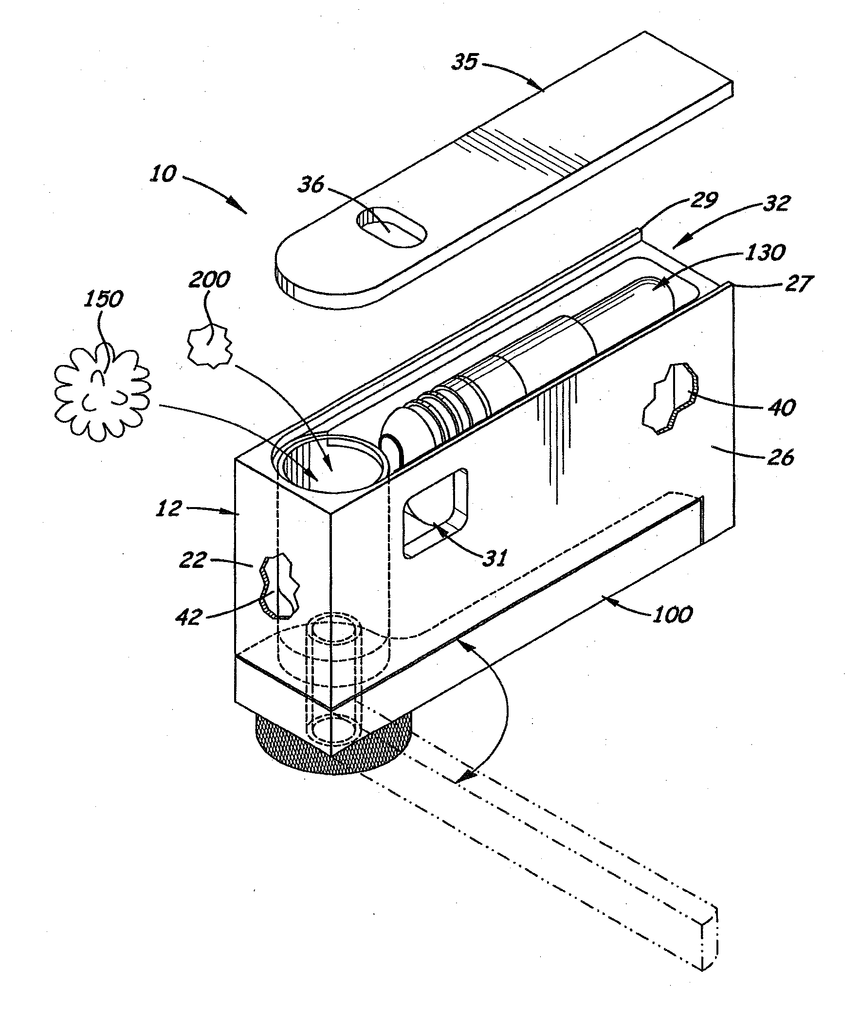
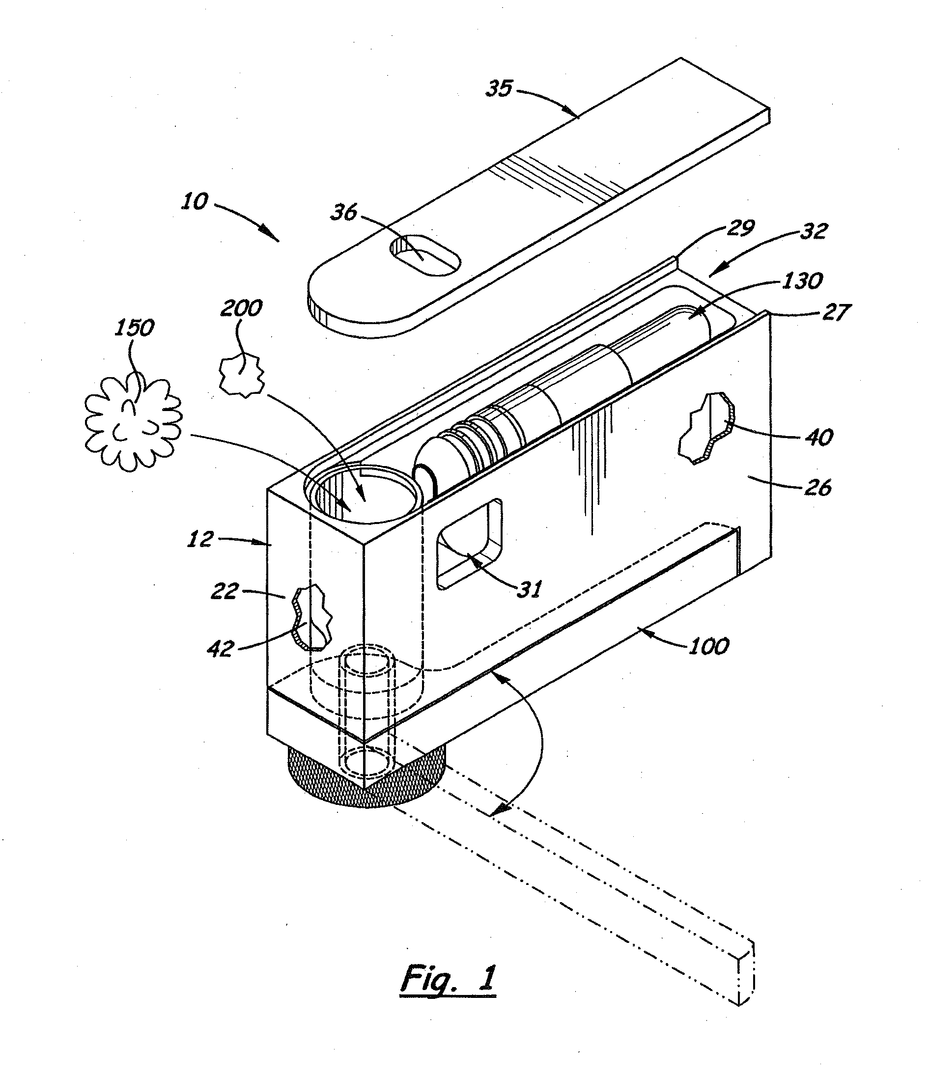
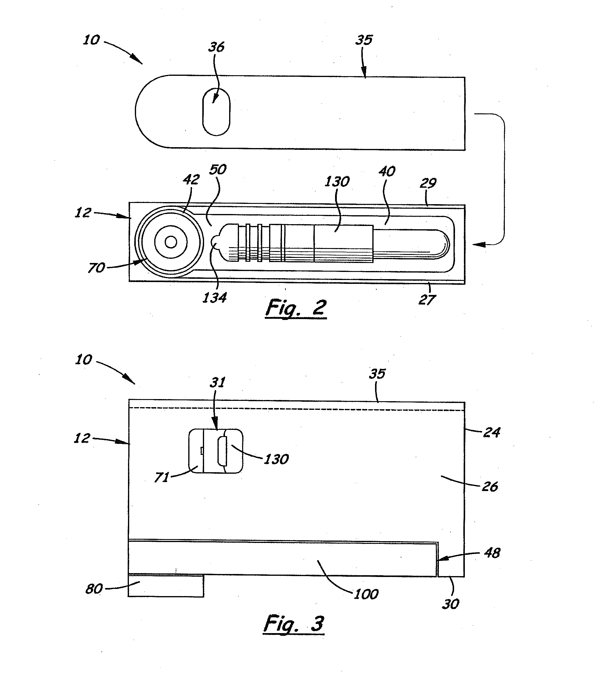
[0053]Shown in the accompanying FIGS. 1-6 is the first embodiment of an auto-igniting smoking pipe, indicated by the reference number 10 with a built-in lighter 130 longitudinally aligned inside a lighter cavity 40 formed inside an elongated body 12. When the pipe 10 is used for smoking, the lighter 130 is automatically activated to continuously produces a flame against the upper bowl 71 formed on the bowl assembly 70 located inside a bowl cavity 42 and filled with a smoking substance 150. When smoking is discontinued, the lighter 130 is automatically de-activated thereby terminating the flame and discontinuing combustion.

[0054]The lighter cavity 40 is located behind a vertically aligned bowl cavity 42 also formed on the front section of the elongated body 12. Formed between the lighter cavity 40 and the bowl cavity 42 is a short wall partition 50 (see FIG. 2). In the preferred embodiment, the bowl cavity 42 is a cylindrical bore with a co-axially aligned hole 54 formed therein. Fo...


PUM


Abstract

A smoking pipe comprising an elongated body with a removable chassis located therein. Located on the chassis is a lighter with an activation switch and flame opening located on one end. The lighter is positioned in the chassis so that the lighter's flame opening is located adjacent to the upper bowl on the bowl assembly also mounted on the chassis. Formed over the upper bowl are air openings which allow heated hot gas to enter the bowl and vaporize or burn material placed therein Rotatably mounted on the lower neck on the bowl assembly is a ratchet. Attached to the ratchet is an elongated mouthpiece. The ratchet which includes a cam surface with a hook formed thereon that engages the distal end of a pawl. The proximal end of the pawl sits in a receiving cavity form a moveable head also mounted on the chassis that selectively presses against the activation switch on the lighter. The relative locations of the cam surface, smoke bores on the bowl assembly, and the mouthpiece are designed so that less movement of the mouthpiece is required to activate the lighter.

Description

[0001]This is a continuation in part application of U.S. utility patent application (Ser. No. 11 / 236,344), filed on Sep. 27, 2005.BACKGROUND OF THE INVENTION[0002]1. Field of the Invention[0003]This invention relates to smoking pipes and more particularly, to smoking pipes used with tobacco or medicinal containing chemicals that require a constant ignition source for combustion.[0004]2. Description of the Related Art[0005]It is known that inhalation administration is a well known method for delivering medications to the body. With some medication, inhalation administration is preferred due to its faster onset of activity and because it bypasses the gastrointestinal and hepatic systems that can destroy or deactivate some medications.[0006]Some chemicals, such as nicotine, are natural occurring substances found in tobacco plants that are released when the plant is burned. The released chemical is distributed in the smoke that when inhaled, is absorbed through the lungs and into the bo...

Claims


Application Information

Patent Timeline
IPC IPC(8): A24F3/00
CPCA24F3/00
Inventor JONES, MIKE
Owner JONES MIKE
Learn More