Portable UV monitoring device
a monitoring device and portability technology, applied in the direction of optical radiation measurement, fluorescence/phosphorescence, instruments, etc., can solve the problems of increasing cost and manufacturing complexity, offering a crude indication of the total dose, and suffering from drawbacks
- Summary
- Abstract
- Description
- Claims
- Application Information
AI Technical Summary
Problems solved by technology
Method used
Image
Examples
embodiments
Embodiment 1
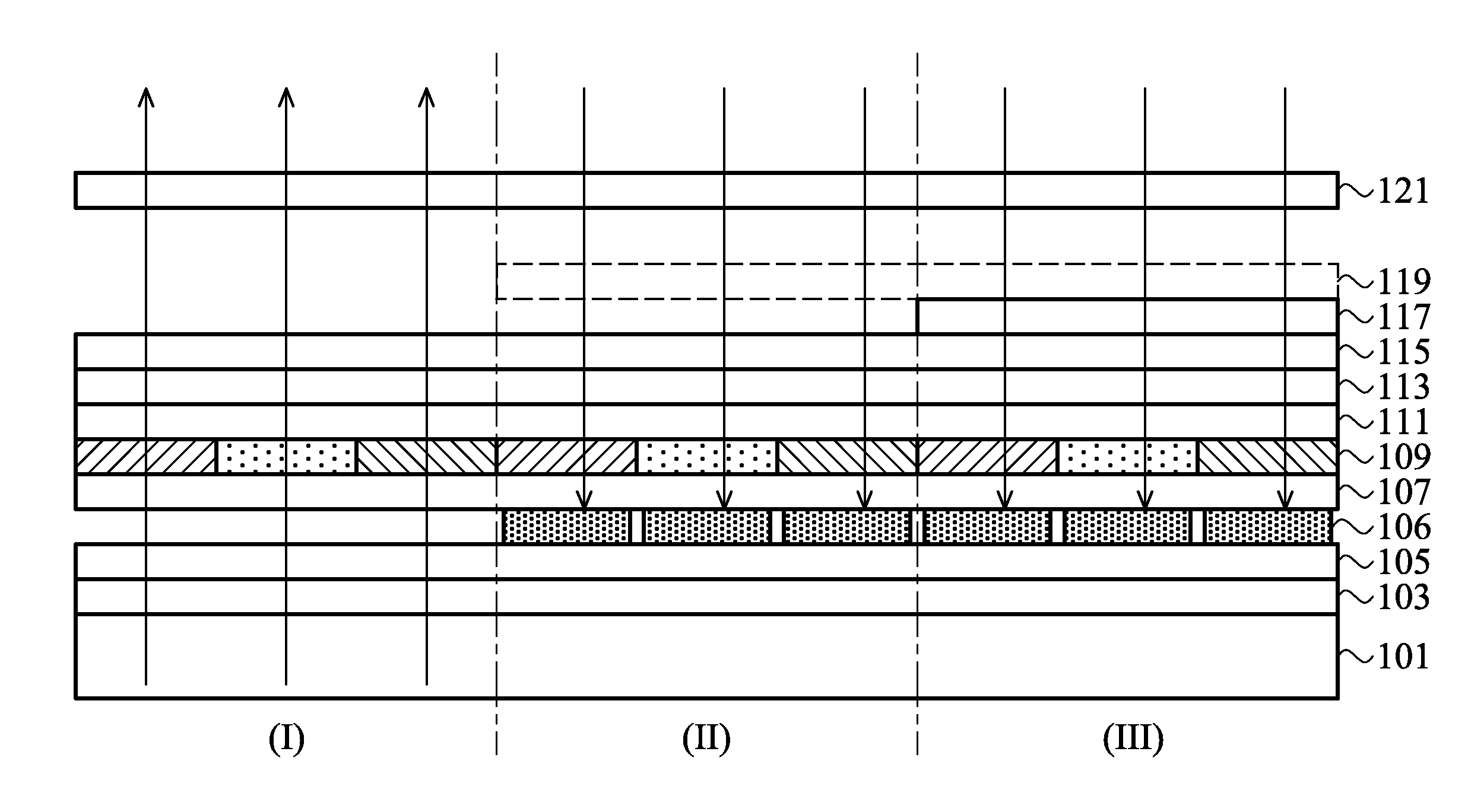
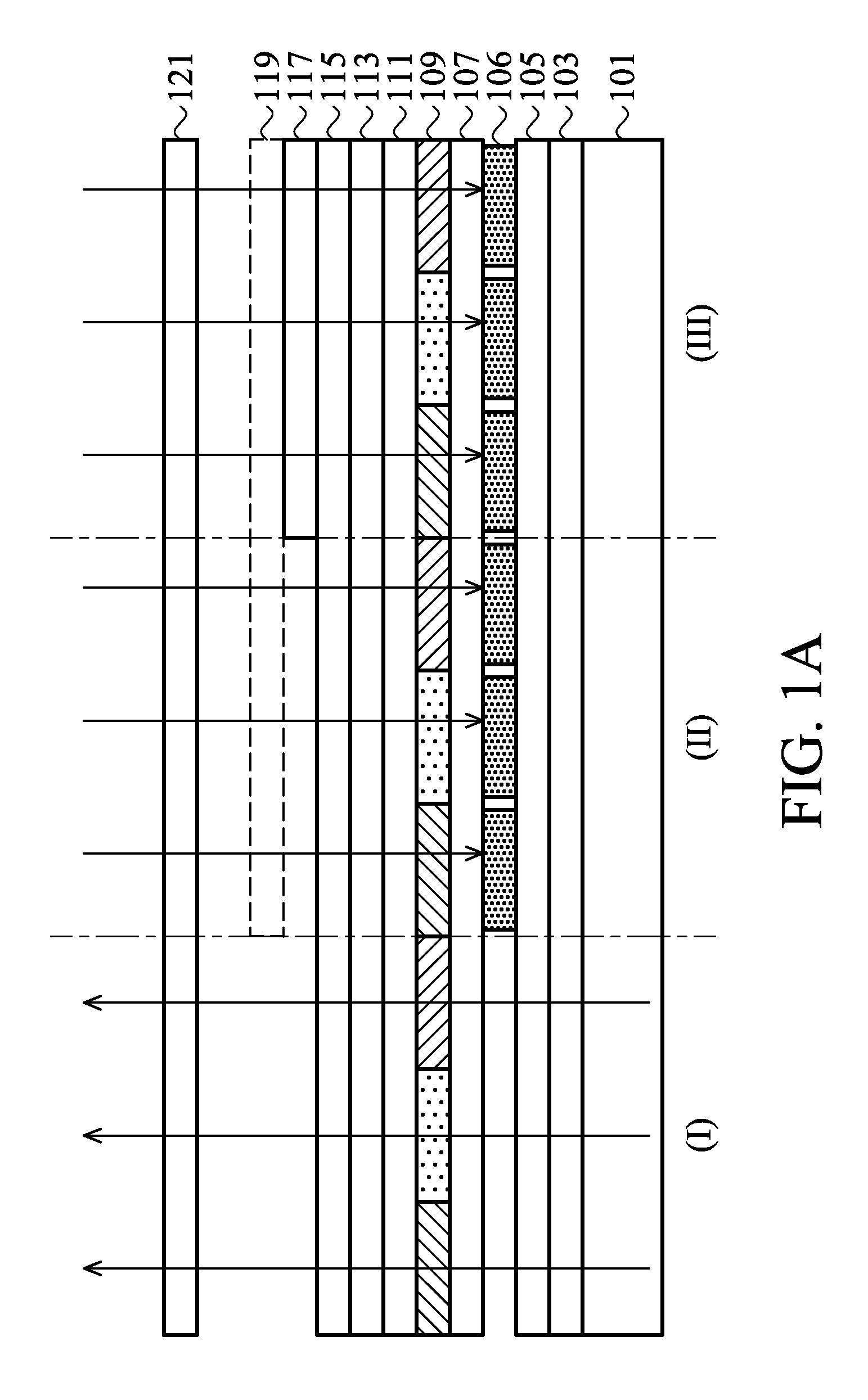
[0023]The construction of a UV monitoring device is shown in FIG. 1A. The device of the FIG. 1A is subdivided into three regions in order to illustrate the differences from a standard mobile display construction. In the left third of FIG. 1A is the standard display region (I) in which light from the backlight 101 passes through the polarizer 103, through the array substrate 105 having a plurality of TFT arranged in array, has its intensity modulated by the liquid crystal layer 107, then passes through the color filter layer 109 on its top substrate 111 to generate the required intensity (the relative transmission of each RGB component within a pixel determining the net color and spectral content of the pixel), and finally passes through the compensation and bright enhancement films 113 and polarizer 115 where it is seen by the user.
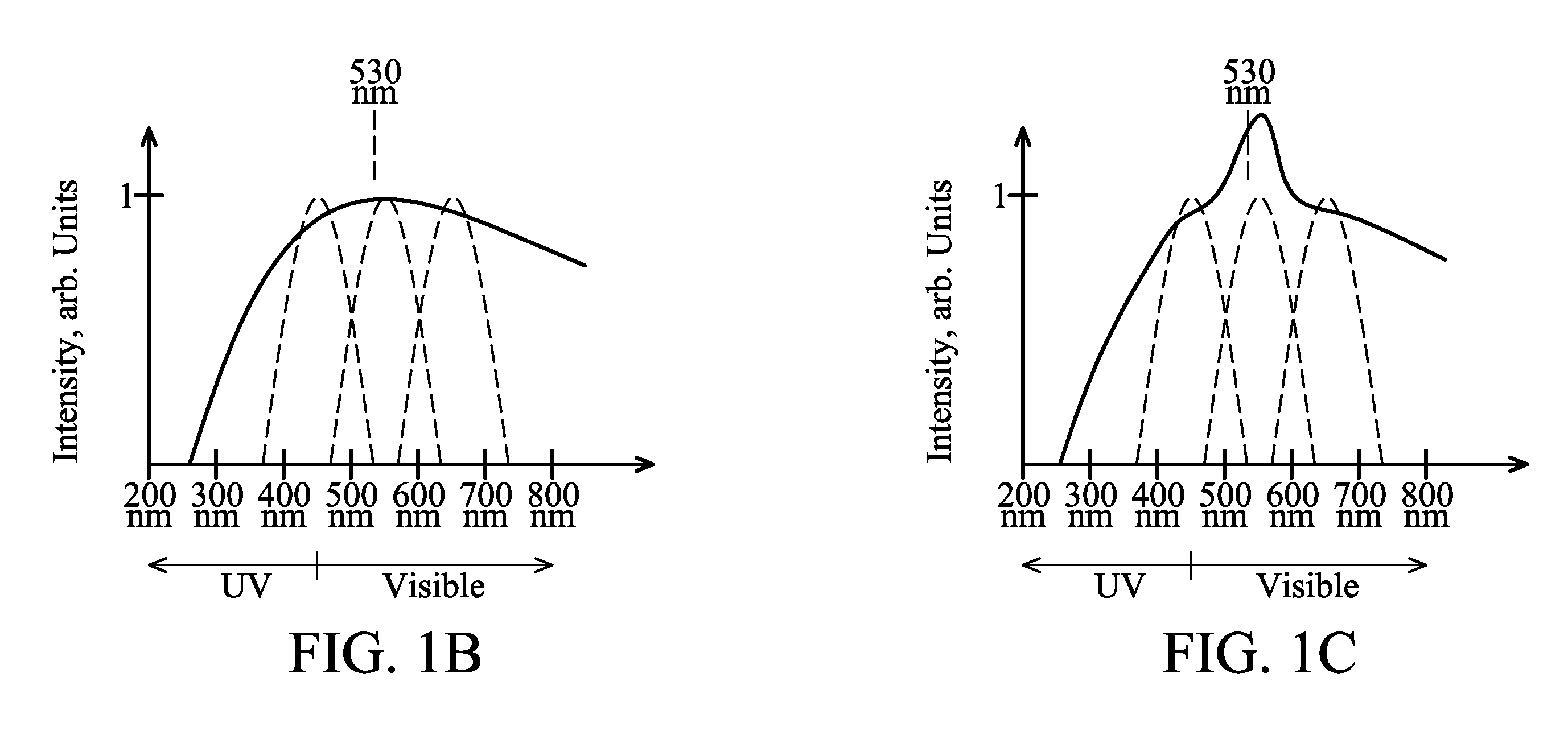
[0024]The reference region (II) is used to monitor the intensity of the red, green, and blue components of visible light in the background ra...
embodiment 2
[0029]Embodiment 2 incorporates a UVA filter (not shown) on the optical radiation side of the fluorescent dye layer 117. The filter selectively absorbs only the UVA radiation and therefore prevents it from contributing to the detected signals. Such dyes are available commercially and can be incorporated into various polymers such as Plexiglass and polycarbonate which is in widespread use in products such as sunglasses.
embodiment 3
[0030]In Embodiment 1, the display mode of the display region (I) is transmissive or transflective type, and the pixel electrode of the array substrate 105 must be all transparent or semi-transparent to match the backlight. In Embodiment 3, the display mode of the display region (I) is reflective type, wherein the pixel electrode of the array substrate 105 is reflective material such as metal. As shown in FIG. 6, the backlight 101 and the polarizer 103 in FIG. 1A are omitted in Embodiment 3.
PUM
 Abstract
Description
Claims
Application Information
 - R&D
- Intellectual Property
- Life Sciences
- Materials
- Tech Scout
- Unparalleled Data Quality
- Higher Quality Content
- 60% Fewer Hallucinations
Browse by: Latest US Patents, China's latest patents, Technical Efficacy Thesaurus, Application Domain, Technology Topic, Popular Technical Reports.
© 2025 PatSnap. All rights reserved.Legal|Privacy policy|Modern Slavery Act Transparency Statement|Sitemap|About US| Contact US: help@patsnap.com


