Connector assembly for a trailer
a technology for connecting parts and trailers, which is applied in the field of connecting parts for trailers and the system for aligning connectors on trailers, can solve the problems of difficult alignment of trailer connectors, time-consuming and awkward process, and the weight of the trailer with the boat is hundreds of pounds
- Summary
- Abstract
- Description
- Claims
- Application Information
AI Technical Summary
Benefits of technology
Problems solved by technology
Method used
Image
Examples
first embodiment
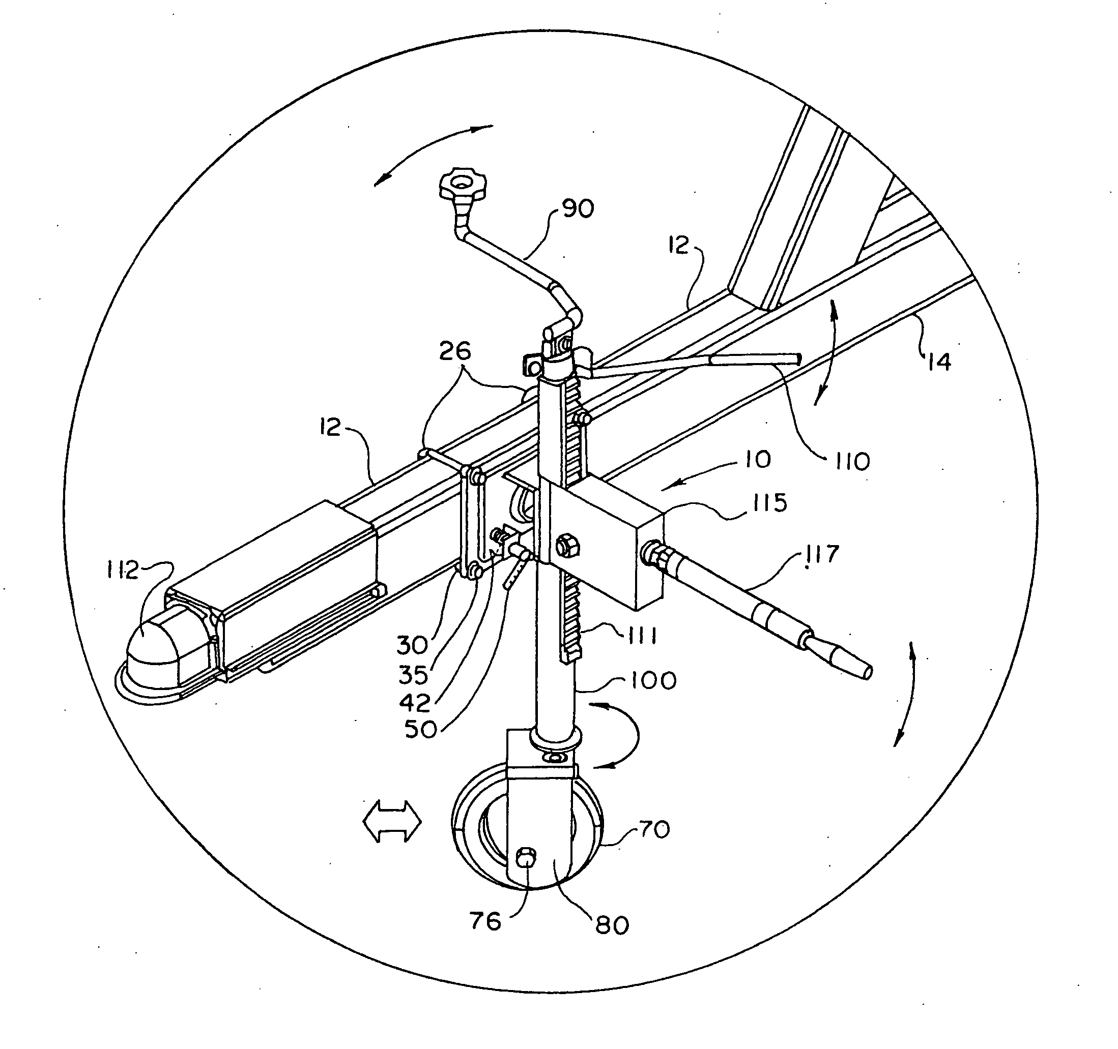
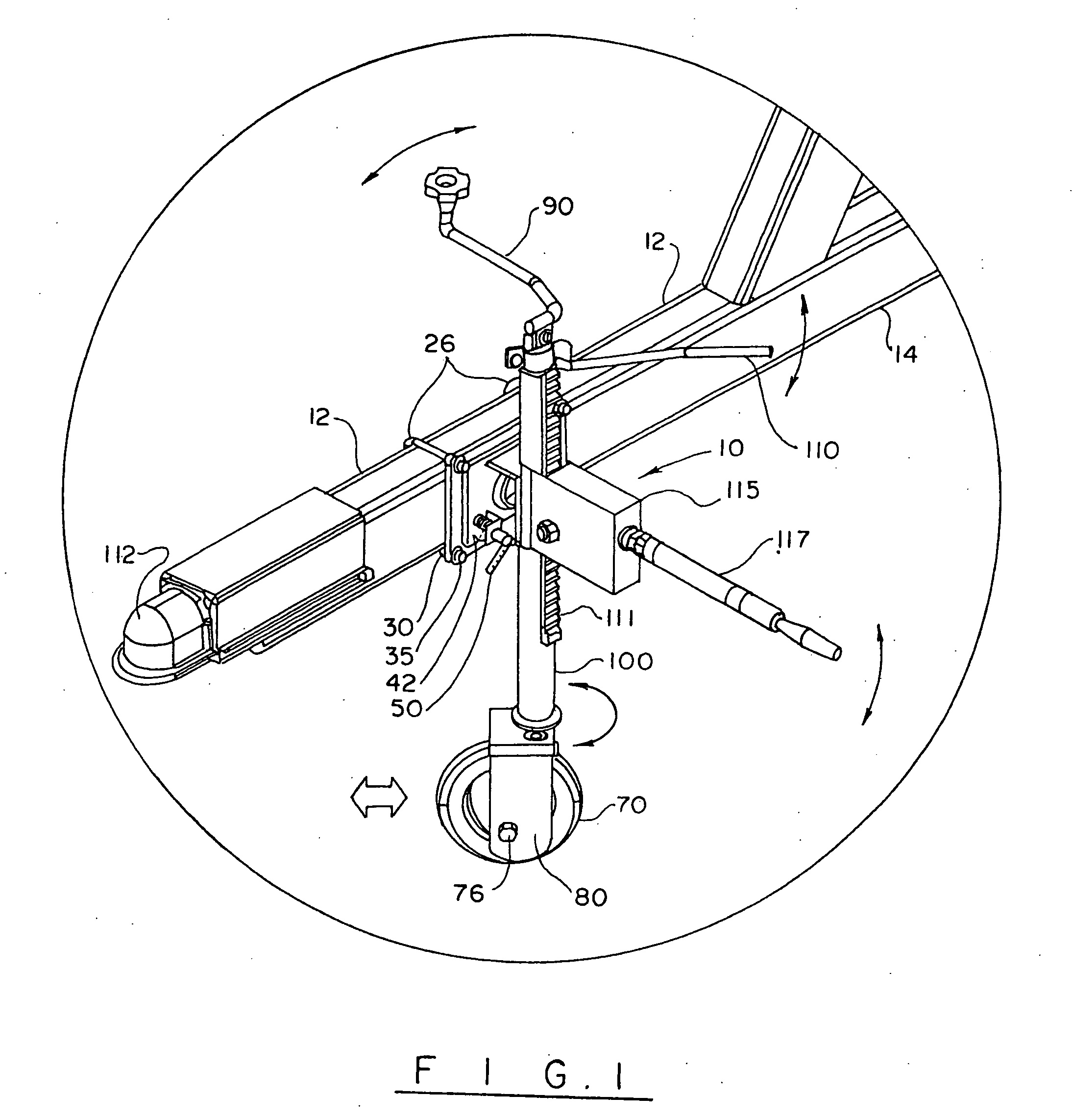
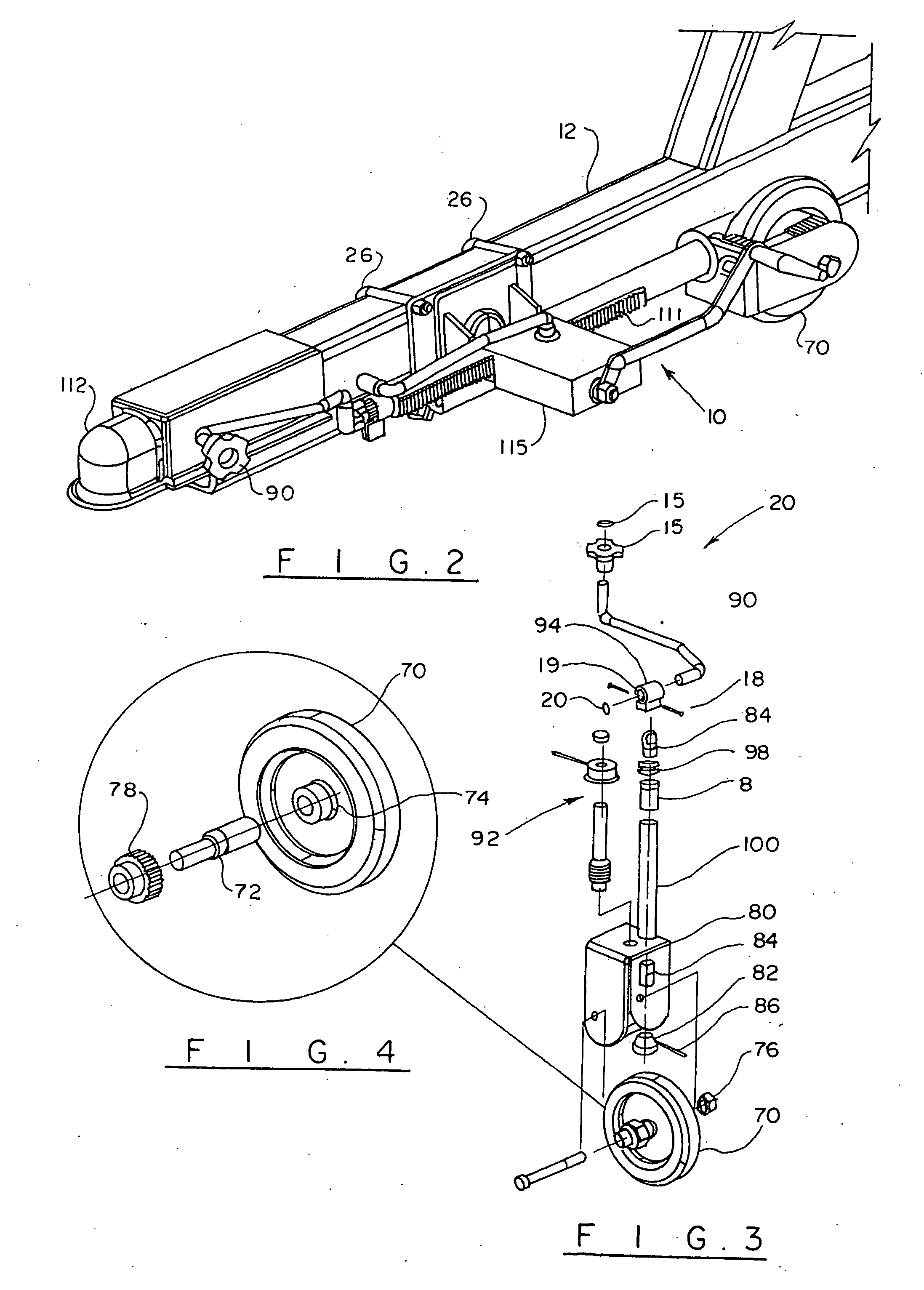
[0032]Turning now to the drawings in more detail, numeral 10 designates the trailer connector assembly of the present invention. The trailer connector assembly 10 is adapted for securing on a connector arm 12 of a trailer 14. The connector assembly 10 comprises a drive assembly 20, a steering assembly 22 and a tilt assembly 24, which in combination provide motion flexibility to the connector assembly 10 and allow the connector assembly to move along a vertical axis, side-to-side and forward and backward.
[0033]Turning to FIG. 6, the tilt assembly 24 is shown in more detail. The tilt assembly 24 comprises a mounting means, which secures the connector assembly 10 on the connector arm 12. In this embodiment, the mounting means comprises a pair of U-shaped bolts 26 that have their free ends 27, 28 extend around the connector arm 12 and engage with a tilt base plate 30 through corresponding aligned openings 31, 32. The bolts 31, 32 are secured to the tilt base plate by washers 33 and nuts...
second embodiment
[0043]Turning now to the second embodiment shown in FIG. 7, the connector assembly 120 is shown to comprise a similar mounting assembly comprised of one or more mounting U-bolts 122 engageable with the a base plate 124 and a tilting plate 126. A pull tilt pin 125 functions in a manner similar to the tilt pin 50. A drive shaft is positioned in a housing 130, the outside of which carries a rack 131. A mating pinion / gear is positioned in a housing 132, and a handle 134 is provided for moving the pinion / gear along the rack 131.
[0044]In this embodiment, the hand-operated crank and drive assembly is replaced with a motor 136, which is mounted in operational connection with the rotating wheel 70. The motor 136 is powered by a battery 138, which can be positioned on the trailer 14. A suitable wiring 137 connects the motor 136 with the battery 138 to facilitate movement of the connector assembly 120 toward and away from the hitch of the towing vehicle. Similarly to the connector assembly 10,...
third embodiment
[0045]FIGS. 8-16 illustrate the apparatus of the present invention, which is generally designated by numeral 150. This embodiment employs a pair of motors, a drive wheel motor 152 and a steering motor 154 to drive and steer the connector assembly and thus the connector arm 12 for proper alignment with a hitch of a towing vehicle 156. The motors 152, 154 are operationally connected to a power source of the vehicle 156 through a suitable cable assembly 159.
[0046]Similarly to the embodiments of FIGS. 1-7, the connector assembly 150 can be mounted on the connector arm 12 of the trailer 14 by the mounting means 157, which can be a pair of U-bolts that are secured on the connector arm 12 by bolts 158 or other suitable securing means. The ends of the U-bolts extend through corresponding openings formed in the tilt base plate 160, which is engaged with the pivotally rotatable tilting plate 162.
[0047]A drive shaft housing 164 is secured to the tilting plate 162 allowing the housing 164 to be...
PUM
 Abstract
Description
Claims
Application Information
 - R&D
- Intellectual Property
- Life Sciences
- Materials
- Tech Scout
- Unparalleled Data Quality
- Higher Quality Content
- 60% Fewer Hallucinations
Browse by: Latest US Patents, China's latest patents, Technical Efficacy Thesaurus, Application Domain, Technology Topic, Popular Technical Reports.
© 2025 PatSnap. All rights reserved.Legal|Privacy policy|Modern Slavery Act Transparency Statement|Sitemap|About US| Contact US: help@patsnap.com


