Trainable Robot and Method of Training

a robot and training method technology, applied in the field of training robots and methods, can solve the problems of increasing non-linearly the time required for training, tedious and time-consuming training protocols, and wasting tim

Inactive Publication Date: 2010-07-29
AGILENT TECH INC
View PDF4 Cites 15 Cited by
  • Summary
  • Abstract
  • Description
  • Claims
  • Application Information

AI Technical Summary

Problems solved by technology

This training protocol is tedious and time consuming
Even with the simplification just described, the training protocol remains tedious and time con...

Method used


Image

  • Trainable Robot and Method of Training
  • Trainable Robot and Method of Training
  • Trainable Robot and Method of Training

Examples


Embodiment Construction

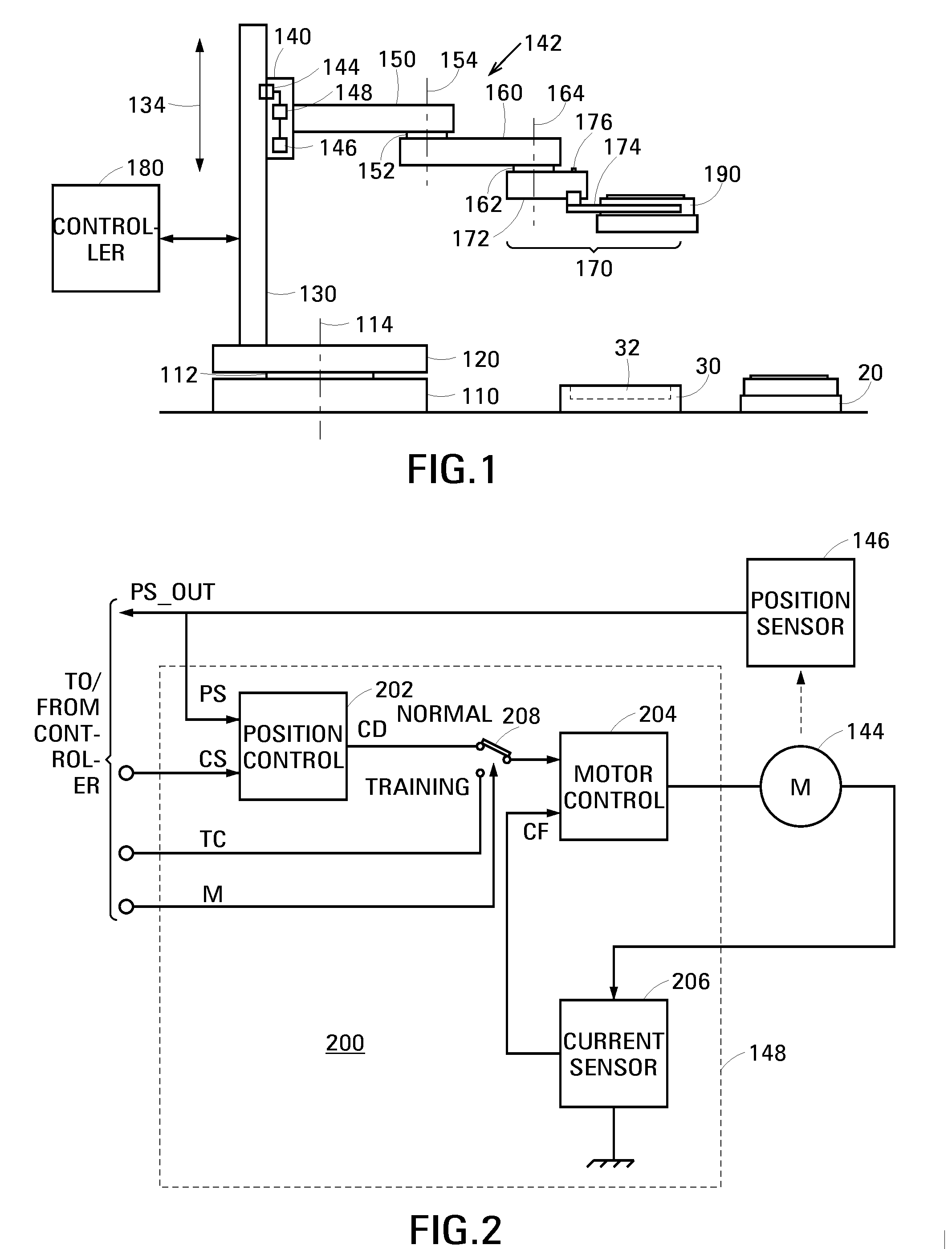
[0018]A robot in accordance with an embodiment of the invention comprises a movable member, a motor operable to change a position of the movable member relative to a gravitationally-loaded axis, and a servo operable to control the motor. The servo has a normal operational mode in which it controls the motor to define the position of the movable member relative to the gravitationally-loaded axis. The servo additionally has a training mode in which it controls the motor to set the movable member to a weightless state. In its weightless state, a user can easily and accurately move the movable member to train the robot.

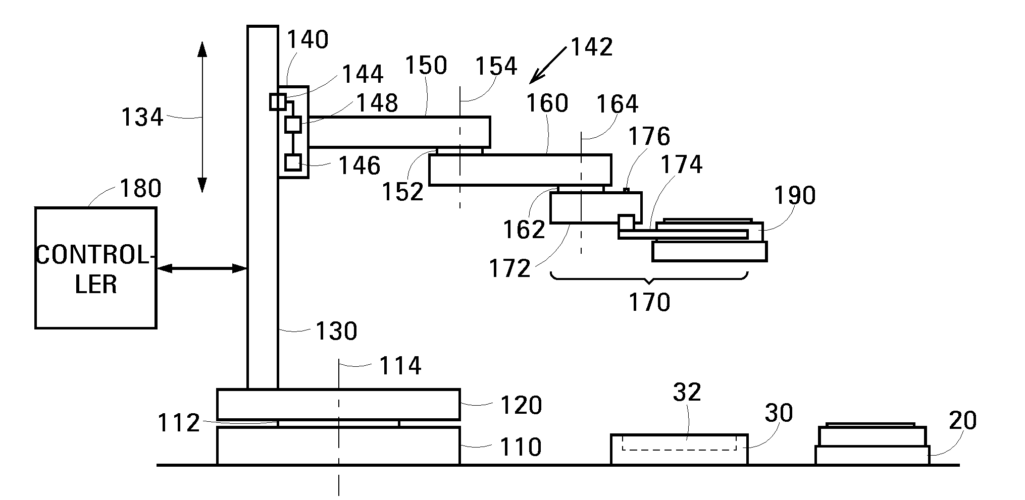
[0019]FIG. 1 is a schematic drawing showing an example 100 of a pick-and-place robot in accordance with an embodiment of the invention. Robot 100 is composed of a mounting 110, a base 120, an elongate track 130, a stage 140, an upper arm 150, a forearm 160, an end effector 170 and a controller, schematically shown at 180. Base 120 and track 130 as a unit, stage 140 and up...


PUM


Abstract

The robot comprises a movable member; a motor operable to change a position of the movable member relative to a gravitationally-loaded axis; and a servo operable to control the motor. The servo has a normal operational mode in which it controls the motor to define the position of the movable member relative to the gravitationally-loaded axis. The servo additionally has a training mode in which it controls the motor to set the movable member to a weightless state. In its weightless state, a user can easily and accurately move the movable member to train the robot.

Description

BACKGROUND [0001]Robots are used to perform many repetitive tasks in research and manufacturing. Once class of robot known as a pick-and-place robot is configured to pick up a payload at an origin location, to move the payload to a destination location and to deposit the payload at the destination location.[0002]A robot is typically composed of a number of mechanical elements that are capable of moving relative to one another to enable the robot to move an object, which will be referred to below as a payload, along a defined path, e.g., from a source location to a destination location. The mechanical elements will be referred to herein as members. To allow a first member of the robot to move relative to a second member, the members are attached at a junction having between one and six (three in translation, three in rotation) degrees of freedom.[0003]A motor for each degree of freedom provides a motive force to move the second member relative to the first member in its respective de...

Claims


Application Information

Patent Timeline
IPC IPC(8): G05B19/423
CPCB25J9/1656G05B19/423G05B2219/41114G05B2219/36433G05B2219/36422
Inventor YOUNG, DEREKWAGNER, JON
Owner AGILENT TECH INC
Why Eureka
Try Eureka