Electrohydraulic valve servomechanism with adaptive resistance estimator

a technology of adaptive resistance and electric current, which is applied in the direction of electric controllers, servomotors, instruments, etc., can solve the problems of difficult control of electric current and difficulty in precise control of electric curren

Inactive Publication Date: 2005-09-29
HUSCO INT INC
View PDF14 Cites 25 Cited by
  • Summary
  • Abstract
  • Description
  • Claims
  • Application Information

AI Technical Summary

Benefits of technology

[0012] A servomechanism that operates an electrohydraulic valve includes a stage that estimates the resistance of a coil in the valve and adjusts the level of electric voltage applied to the valve in response to changes of that resistance estimate.
[0013] The servomechanism receives a current setpoint which designates a desired level of electric current to be applied to a coil of the electrohydraulic valve and also senses an actual level of electric current flowing through the coil. A proportional term is produced based on a current error obtained from current setpoint and the actual level of electric current. The actual level of electric current also is used to produce a coil resistance value. The coil resistance value and the proportional term are employed to derive a desired voltage level for the coil which then is used to generate a PWM signal for driving the coil.
[0014] Preferably, the coil resistance value is derived by determining an estimated resistance based on the actual level of electric current and a previous desired voltage level. A resistance error then is determined as the difference between the estimated resistance and a previous coil resistance value. The resistance error is multiplied by an observer gain value and the result is added to the previous coil resistance value to produce a new coil resistance value.
[0015] In a preferred embodiment, a desired voltage level is derived by multiplying the new coil resistance value by the current setpoint and adding the product to the proportional term. A derivative term also may be added to produce the desired voltage level. That derivative term is obtained by multiplying a derivative gain value by a derivative of the current error.

Problems solved by technology

However, it is difficult to precisely control the electric current.
In addition, operation of the solenoid and the valve elements tend to be non-linear which makes their modeling difficult for control purposes.

Method used


Image

  • Electrohydraulic valve servomechanism with adaptive resistance estimator
  • Electrohydraulic valve servomechanism with adaptive resistance estimator
  • Electrohydraulic valve servomechanism with adaptive resistance estimator

Examples


Embodiment Construction

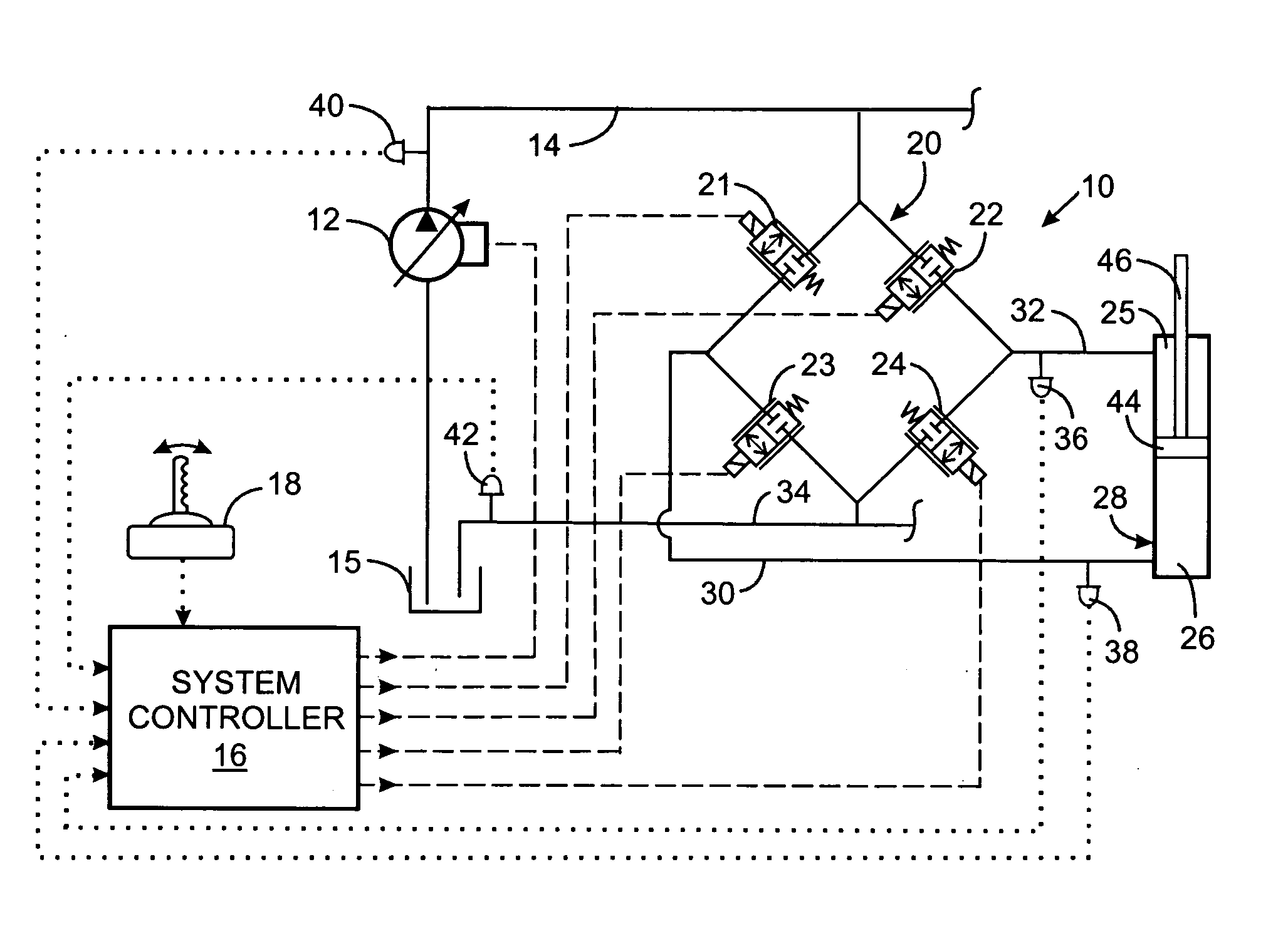
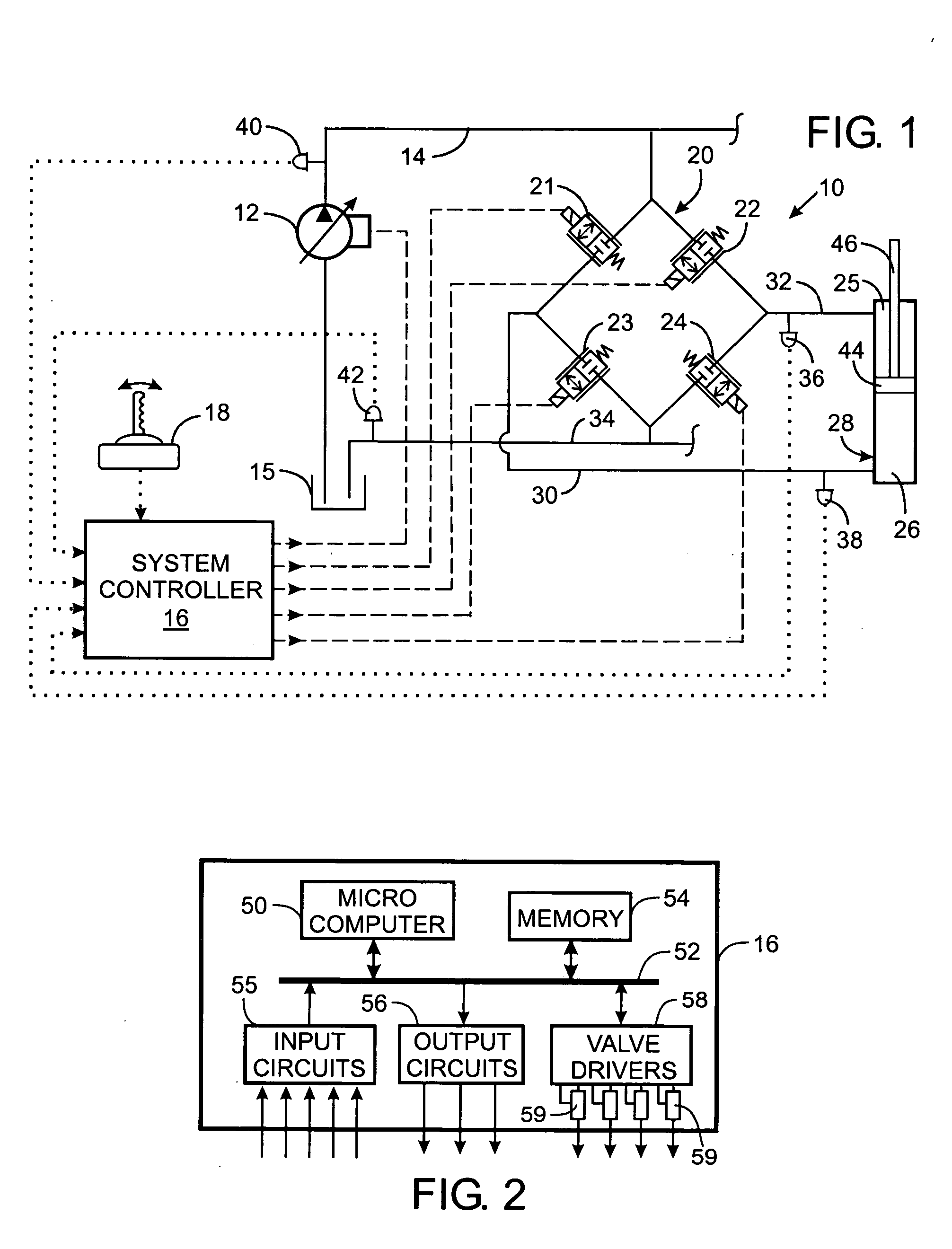
[0019] With initial reference to FIG. 1, a machine such as an agricultural or construction vehicle has mechanical members that are operated by a hydraulic system. The hydraulic system 10 includes a variable displacement pump 12 that is driven by a motor or engine (not shown) to draw hydraulic fluid from a tank 15 and furnish the hydraulic fluid under pressure into a supply line 14.

[0020] The supply line 14 is connected to a valve assembly 20 comprising four proportional electrohydraulic (EH) valves 21, 22, 23 and 24 that control the flow of hydraulic fluid to and from a hydraulic actuator, such as cylinder 28, in response to electricity from a system controller 16. The first EH valve 21 governs the flow of fluid from the supply line 14 to a first conduit 30 connected to the head chamber 26 of the cylinder 28. The second EH valve 22 selectively couples the supply line 14 to a second conduit 32 which leads to the rod chamber 25 of the cylinder 28. The third EH valve 23 is connected b...


PUM


Abstract

A servomechanism includes a controller which dynamically estimates the resistance of the solenoid coil in an electrohydraulic valve as part of determining a level of electric voltage to apply to open the valve. The servomechanism receives a current setpoint designating a desired electric current level and senses the actual level of current flowing through the coil. A proportional term is derived from the current setpoint and the actual level of current. Creation of a derivative term is based on the difference between the current setpoint and the actual level of current. A feedforward term is produced by estimating the resistance of the electrohydraulic valve and limiting the feedforward term to a predefined range of acceptable values. The proportional term, derivative term, and the feedforward term are summed to define a desired voltage level, and a PWM signal for driving the electrohydraulic valve is generated based on the desired voltage level.

Description

CROSS-REFERENCE TO RELATED APPLICATIONS [0001] This application claims benefit of U.S. Provisional Patent Application No. 60 / 556,115 filed Mar. 25, 2004.STATEMENT REGARDING FEDERALLY SPONSORED RESEARCH OR DEVELOPMENT [0002] Not Applicable BACKGROUND OF THE INVENTION [0003] 1. Field of the Invention [0004] The present invention relates to hydraulic power systems with electrically operated control valves, and more particularly to electrical servomechanisms that control the application of electricity to such valves. [0005] 2. Description of the Related Art [0006] A wide variety of machines have moveable members which are driven by an hydraulic actuator, such as a cylinder and piston arrangement, that is controlled by a hydraulic valve. For example, backhoes have a tractor on which is mounted a boom, arm and bucket assembly with each of those components being driven by one of more cylinder-piston arrangements. The flow of fluid to and from each hydraulic actuator is controlled by a hydr...

Claims


Application Information

Patent Timeline
Patent Type & Authority Applications(United States)
IPC IPC(8): F15B11/04E02F9/22F15B11/00F15B19/00F15B21/08F16K31/02F16K37/00G05D7/06
CPCE02F9/22F15B11/006F15B19/00F16K37/0083F15B2211/30575F15B2211/328F15B2211/875F15B21/087
Inventor TABOR, KEITH A.PFAFF, JOSEPH L.
Owner HUSCO INT INC
Why Eureka
Try Eureka