
Load balancing of parallel connected inverter modules

Active Publication Date: 2010-07-29
ABB (SCHWEIZ) AG
View PDF9 Cites 12 Cited by
  • Summary
  • Abstract
  • Description
  • Claims
  • Application Information

AI Technical Summary

Benefits of technology

[0016]According to exemplary embodiments, current imbalance can be kept within a certain limit and the temperatures of the different output modules can also be kept in control. The fact that the currents are not completely balanced is of less importance since the current imbalance, if not taken into account, may lead to premature wear or sudden destruction of the components due to heating up of the components. When the temperatures of the components are taken into account in current balancing, the parallel currents do not have to be equal in magnitude.

Problems solved by technology

Such a current imbalance can stress the components unevenly and wear switch components with higher current prematurely.
The parallel operated switch components can still be unevenly worn even if the currents have been balanced.
The modification of the control pulses for balancing the currents on the basis of current measurement may thus lead to a situation in which the switch component is damaged due to an excessive temperature.

Method used


Image

  • Load balancing of parallel connected inverter modules
  • Load balancing of parallel connected inverter modules
  • Load balancing of parallel connected inverter modules

Examples


Embodiment Construction

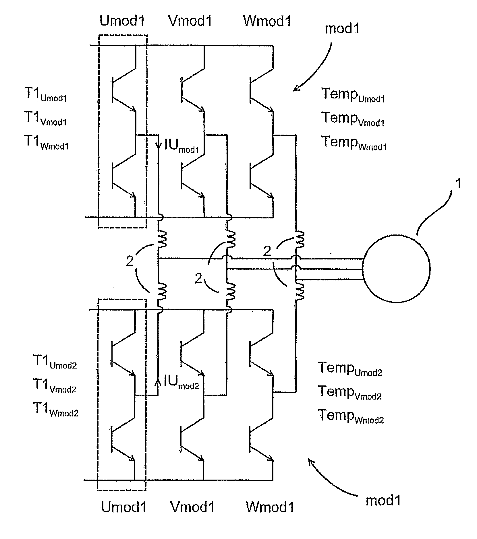
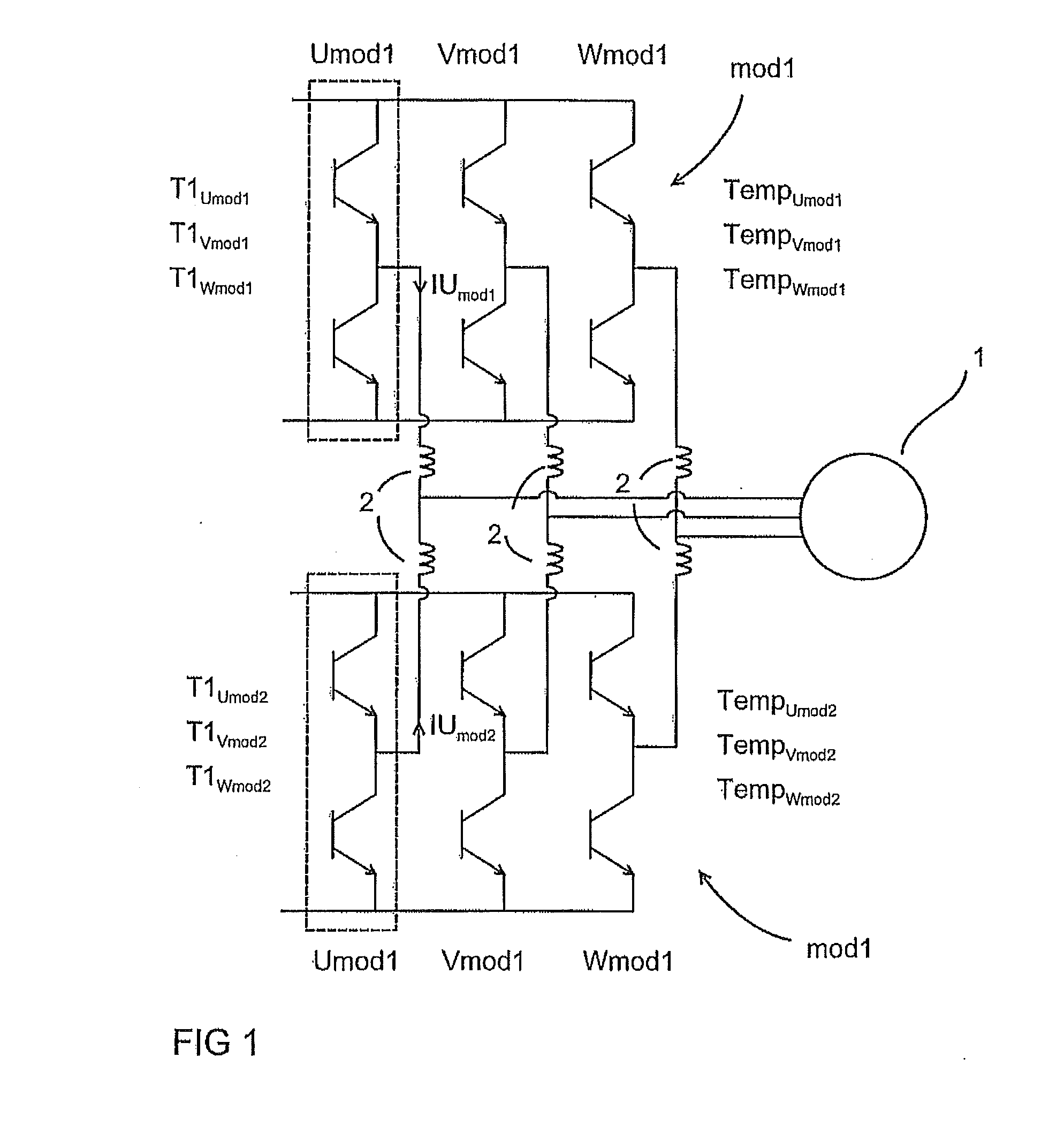
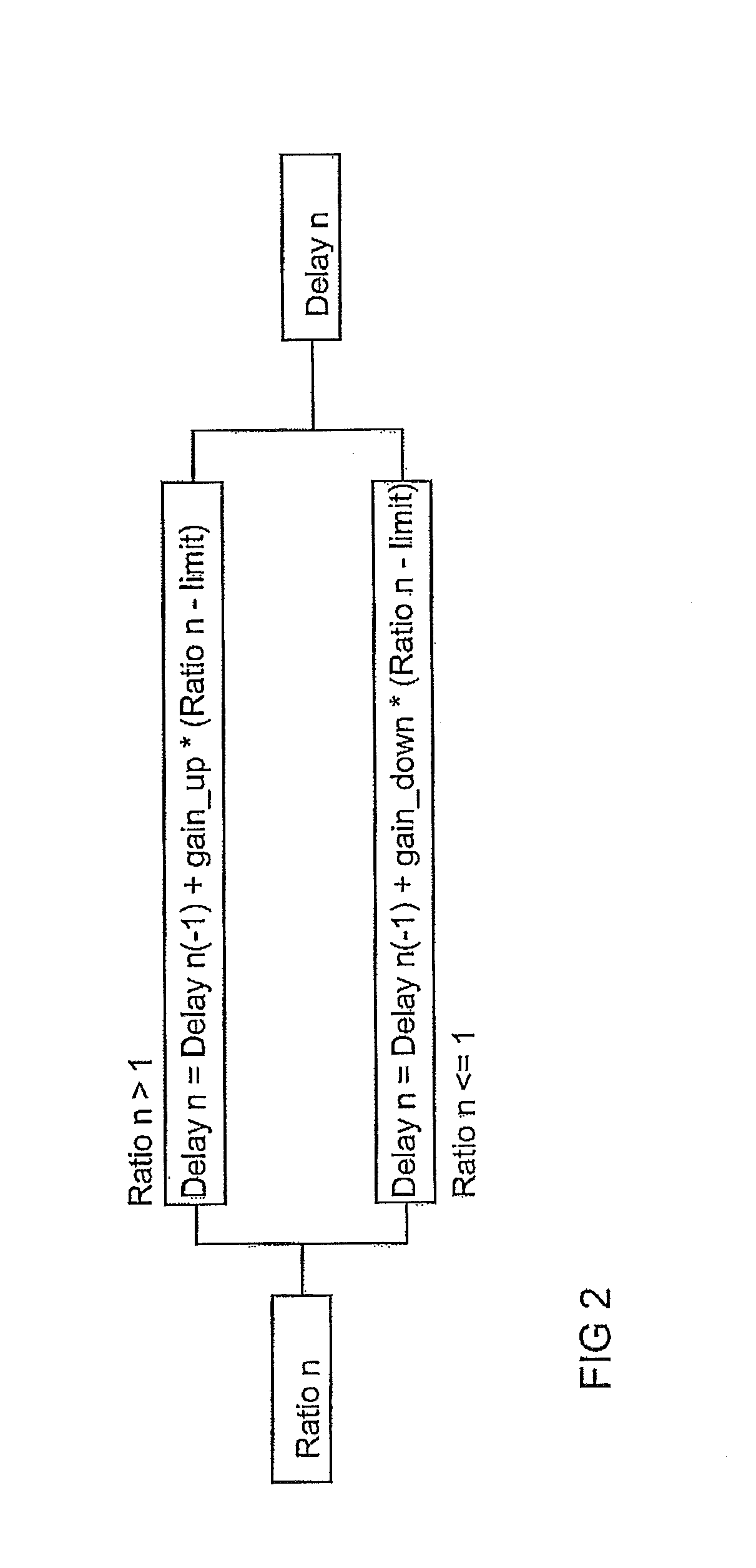
[0015]Exemplary embodiments as discussed herein are based on the idea of balancing the loading between parallel inverter modules by modifying the turn-on or turn-off pulses on the basis of current imbalance and temperature differences between the modules. As disclosed herein, the currents between the inverter modules need not be driven to same value if the temperatures of the modules differ from each other.

[0016]According to exemplary embodiments, current imbalance can be kept within a certain limit and the temperatures of the different output modules can also be kept in control. The fact that the currents are not completely balanced is of less importance since the current imbalance, if not taken into account, may lead to premature wear or sudden destruction of the components due to heating up of the components. When the temperatures of the components are taken into account in current balancing, the parallel currents do not have to be equal in magnitude.

[0017]FIG. 1 shows two parall...


PUM


Abstract

A method and an arrangement are disclosed for balancing load between parallel connected inverter modules, which inverter modules are arranged to supply a common load. The method can include providing similar switching instructions for parallel connected inverter modules, determining on the basis of phase currents of each parallel inverter module a first time period for each output phase of each inverter module for correcting current imbalance by advancing or delaying turn-on or turn-off time instants of switch components of the inverter modules, and advancing or delaying the turn-on or turn-off time instants of the switching instructions based on the first time period. The method also can include determining temperatures of each output phase of each inverter module, modifying the switching instructions for one or more of the parallel inverter modules for controlling the temperatures of the output phases, and controlling the inverter modules with a switching instruction in which the turn-on or turn-off times have been advanced or delayed in respect of one or more parallel modules and further modified in respect of one or more inverter modules.

Description

RELATED APPLICATION[0001]This application claims priority under 35 U.S.C. §119 to European Patent Application No. 09151388.7 filed in Europe on Jan. 27, 2009, the entire content of which is hereby incorporated by reference in its entirety.FIELD[0002]Local balancing inverter modules, for sharing an output current between two or more parallel connected inverter, is disclosed herein, such as modules feeding a common load.BACKGROUND INFORMATION[0003]An inverter is an apparatus that is used for producing an alternating voltage with a variable frequency from a direct voltage source. Inverters can operate by switching either a positive or a negative voltage from the DC voltage source to the load. Output switches of the inverter can be modulated according to a control method for producing a desired voltage to the load. A known application of an inverter is in a frequency converter. Frequency converters, in turn, can be used for driving a motor in a controllable fashion.[0004]In some situati...

Claims


Application Information

Patent Timeline
IPC IPC(8): H03K17/60
CPCH02M7/493H02M1/327H02M1/0043
Inventor KERONEN, JORMAVIRTANEN, REIJOPOYHONEN, SIMO
Owner ABB (SCHWEIZ) AG
Learn More