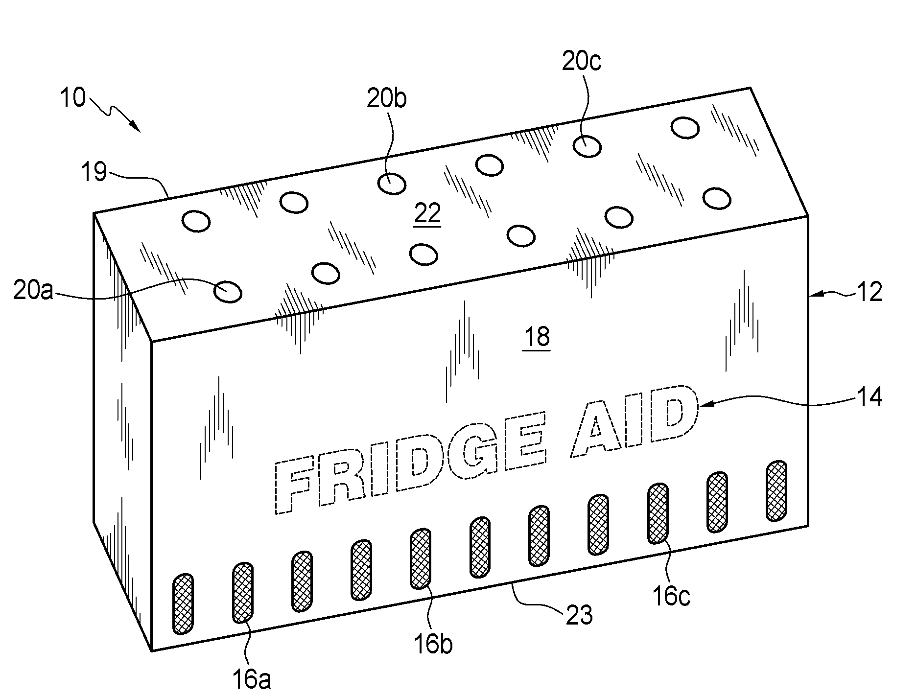
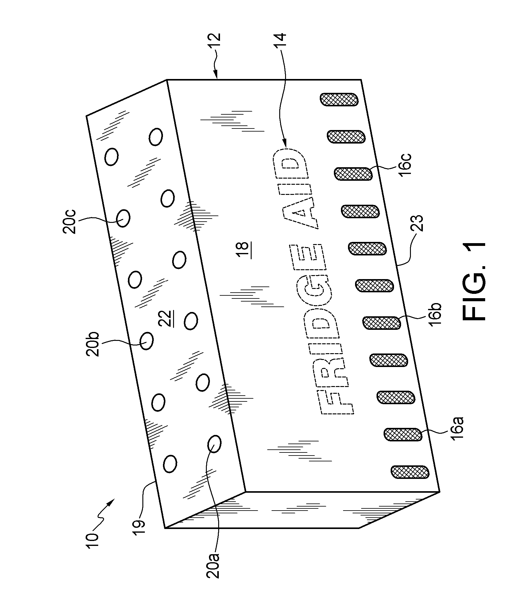
[0033]Referring to the drawings and first to FIG. 1, an improved air deodorizing device 10 for absorbing odor molecules in a refrigerator or freezer is shown. The device 10 includes a housing 12 which is preferably formed from a paper-based construction material such as recycled cardboard. This provides an environmental friendly, biodegradable housing to which designs or trademarks can be readily applied. In this example, a trademark 14 has been applied to the housing 12. FRIDGE AID is a registered trademark of Nu-Rich Enterprises Ltd. of 3338 Venables Street, Vancouver, British Columbia, Canada V5K 2S8. In other examples other trademarks may be applied to the housing 12. For example, the trademark ICE AID may be applied to device which designed for use in the freezer. ICE AID is also a registered trademark of Nu-Rich Enterprises Ltd.
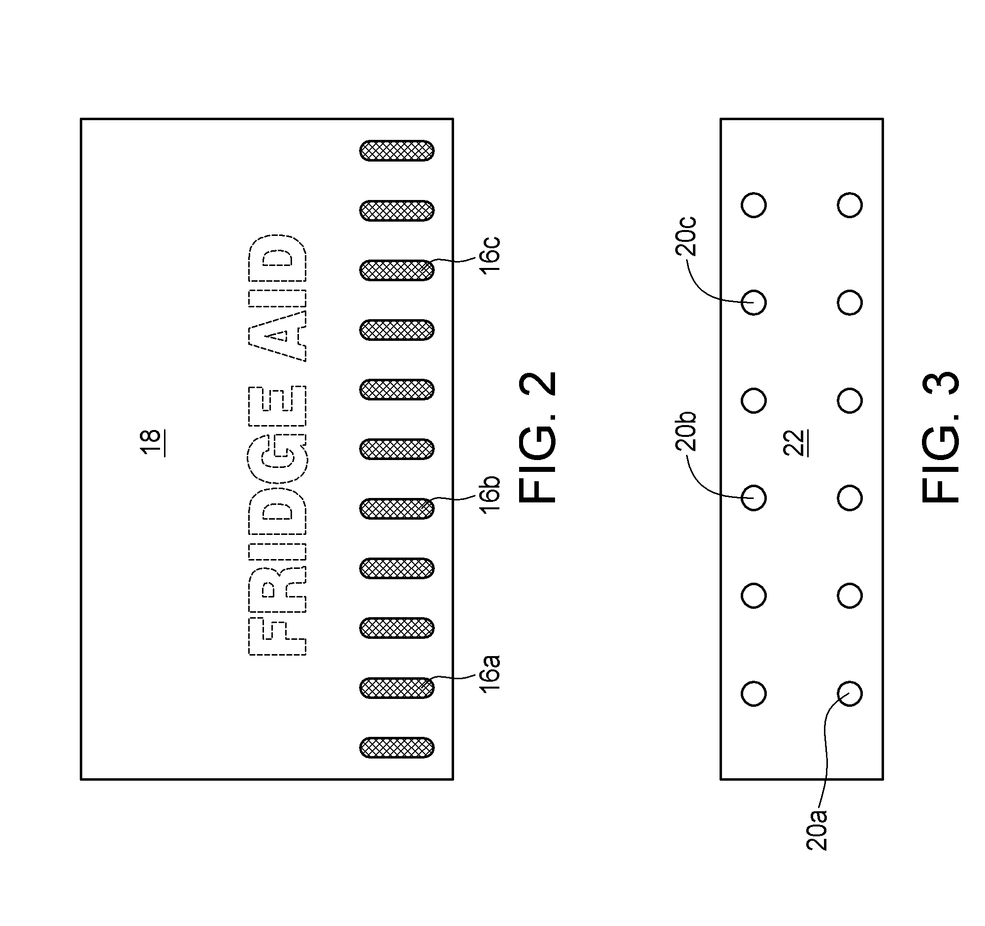
[0034]There is a plurality of openings 16a, 16b, and 16c extending through a first side 18 of the housing 12. There is also a plurality of openings 20a, 20b, and 20c extending through a top 22 of the housing 12. As best shown in FIG. 2, the openings 16a, 16b, and 16c extending through the side 18 of the housing 12 are in the form of spaced apart slots. As best shown in FIG. 3, the openings 20a, 20b, and 20c extending through the top 22 of the housing 14 are in the form of spaced apart circular apertures. It will be understood however that, in other examples, the size, shape, and location of the openings in the housing 12 may vary. The only requirement is that the housing 12 be vented to allow for the flow of air and odor molecules through the housing 12.
[0035]FIG. 1 clearly shows the first side 18 and the top 22 of the housing 12. A second side 19 and a bottom 23 of the housing 12 are best shown in FIG. 13. The first side 18 of the housing 12 and the second side 19 of the housing 12 are mirror images of one another, apart from the trademarks 14 and 15, and have a substantially similar structure which functions in a substantially similar manner. For example, the first side 18 of the housing 12 has a trademark 14 applied thereto and a plurality of openings 16a, 16b, and 16c extending therethrough. Likewise, the second side 19 of the housing 12 has a trademark 15 applied thereto and a plurality of openings 17a, 17b, and 17c extending therethrough. In this example, there are no openings extending through the bottom 23 of the housing 12. It will be understood by a person skilled in the art that the terms “top”, “bottom”, and “side” as used herein are used only in relation to the position of the air deodorizing device 10 as shown in FIG. 1.
[0036]Referring now to FIG. 4, this shows an exploded view of the air deodorizing device 10 and, in particular, an air deodorizing block 24 which is disposed within the housing 12. The air deodorizing block 24 includes a frame 26 and a pair of opposite, permeable walls with only one of the permeable walls 28 being shown in FIG. 4. Another one of the permeable walls 30 is shown in FIG. 9. Similar to the housing 12, the frame 26 is preferably formed from a paper-based construction material such as recycled cardboard. The permeable walls 28 and 30 are preferably formed from a permeable paper-based material such as filter paper which is permeable to odor causing molecules. Non-woven polymeric materials which are permeable to odor causing molecules may also be used.
[0037]A side view of the air deodorizing block 24 is shown in both FIGS. 5 and 6. In FIG. 6 the permeable wall 28, shown in FIG. 5, has been removed. This exposes granular particulates of activated carbon 32 which are retained between the permeable walls 28 and 30. As best shown in FIG. 6, the granular particulates of activated carbon 32 are also retained within a plurality of honeycomb pores 34a, 34b, and 34c which extend between the permeable walls 28 and 30. The honeycomb pores 34a, 34b, and 34c allow the granular particulates of activated carbon 32 to be evenly separated within the air deodorizing block 24 to maximize its absorbency and effectiveness particularly in a low velocity air flow environments as typically found in a refrigerator. The honeycomb pores 34a, 34b, and 34c also minimize pillowing of the permeable walls 28 and 30.
[0038]It is not necessary for the air deodorizing block 24 to be disposed within the housing 12 for the air deodorizing block 24 to be effective. However, the housing 12 will restrict the leakage of activated carbon 32 should the permeable side walls 28 and 30 of the deodorizing block 24 somehow rupture. Furthermore, the housing allows for aesthetically pleasing designs to be applied to the air deodorizing device 10. This is desirable for domestic use. A manufacturer is also able to apply trademarks or advertising to the housing 12 to help boost brand recognition.
[0039]With reference to FIGS. 7 to 13 methods of manufacturing the air deodorizing device 10 disclosed herein will now be described. It will be understood that the methods of manufacturing the air deodorizing device 10 disclosed herein may be accomplished through manual processes, automated processes, or a combination of manual and automated processes.
[0040]FIG. 7 shows a blank 36 which is used to form the frame 26 of the air deodorizing block 24. The blank 36 includes four flaps 38, 40, 42, and 44. Each of the flaps 38, 40, 42, and 44 extends along a respective edge of a border 46 which defines a quadrilateral opening 48 in the blank 36. To form the frame 26, first and second ones of the flaps 38 and 40 are folded 90 degrees along score lines 50 and 52, respectively. The first flap 38 is then further folded 90 degrees along score lines 54 and 56 to form a pair of opposed support tabs. One of these support tabs 58 is shown in FIG. 8. Referring back to FIG. 7, the second flap 40 is also folded 90 degrees along score lines 60 and 62 to form another pair of opposed support tabs.
[0041]After the support tabs are formed, an adhesive or fastener and preferably non-toxic glue is applied to support tabs such that the third and fourth ones of the flaps 42 and 44 may be secured to the support tabs when the flaps 42 and 44 are folded 90 degrees along score lines 64 and 66. This is best shown in FIG. 8 for the fourth flap 44 and one of the support tabs 58. Referring back to FIG. 7 the flaps 38, 40, 42, and 44 are finally folded along score lines 68, 70, 72, and 74 respectively and the corner ends of the of the flaps 38, 40, 42, and 44 are secured together with glue. As shown in FIG. 8, this results in another border 76 defining the quadrilateral opening 48 in the frame 26.
[0042]Referring now to FIG. 9, after the frame 26 is formed; one of the permeable walls 30 is secured to the frame 26. In this example, the border 76 defining the opening 48 in the frame 26 functions as a lip and provides a planar surface onto which glue may be applied. This allows the permeable wall 30 to be easily secured to the frame 26.
[0043]Referring now to FIG. 10 a honeycomb blank 78, which is preferably formed from a paper-based construction material such as recycled cardboard, is cut to an appropriate thickness so as it fit snugly in the between the borders 46 and 76 of the frame 26. In this example, the honeycomb blank 78 is cut to a thickness of between 3 cm and 4 cm, and preferably 3.5 cm; but in other examples other thicknesses may be used. The honeycomb blank 78 is then expanded, as shown in FIG. 11, to open the honeycomb pores 34a, 34b, and 34c and form a honeycomb structure 80. In this example, the honeycomb pores 34a, 34b, and 34c are open ended and open to maximum diameter of 1.5 cm, and preferably 0.6 cm, but in other examples other diameters may be used.
[0044]Glue is applied to one side of the honeycomb structure 80 and it is secured to the permeable wall 30 affixed to the frame 26. The honeycomb pores 34a, 34b, and 34c of the resulting structure, which is shown in FIG. 11, are then be filled with activated carbon as shown in FIG. 6. Glue is then applied to the other side of the honeycomb structure 80 and, as shown in FIG. 5, the other permeable wall 28 is secured to the honeycomb structure 80 to seal the air deodorizing block 24. The air deodorizing block 24 is then inserted into the housing 12 which is formed from a blank 82 shown in FIG. 13. The blank 82 used to form the housing is standard die cut box which is well known in the art and accordingly not described in further detail herein.
[0045]Another method of manufacturing the air deodorizing device 10 disclosed herein includes applying glue to one side of the honeycomb structure 80 and securing it directly to a sheet of permeable paper-based material. The honeycomb structure 80 is then cut into desired lengths and the honeycomb pores 34a, 34b, and 34c are filled with activated carbon. Glue is applied to the other side of the honeycomb structure 80 and the honeycomb pores 34a, 34b, and 34c are sealed with another sheet of permeable paper-based material. The sheets of permeable paper-based material accordingly form the permeable walls 28 and 30 of the air deodorizing block 24. A paper-based trim is cut to the same thickness of the honeycomb structure and glued around the edges of the honeycomb structure 80. The paper-based trim accordingly functions as the frame 26 of the air deodorizing block 24. The air deodorizing block 24 is then inserted into the housing 12 which is formed from a blank 82 shown in FIG. 13.
[0046]It will be understood by a person skilled in the art that many of the details provided above are by way of example only, and are not intended to limit the scope of the invention which is to be determined with reference to following claims.