Implantable Tendon Protection Systems and Related Kits and Methods

Inactive Publication Date: 2010-07-29
ROTATION MEDICAL
View PDF100 Cites 96 Cited by
  • Summary
  • Abstract
  • Description
  • Claims
  • Application Information

AI Technical Summary

Benefits of technology

[0012]In accordance with other aspects of the disclosure, a method is provided which comprises identifying a partially torn portion of a tendon and covering the partially torn portion of the tendon. In some embodiments a device may be positioned over the partially torn portion of the tendon and fixed to the tendon. The device may be fixed to the tendon with adhesive, sutures, staples, and/or anchors. Covering the partially torn portion of the tendon may spread impinging forces across a surface area of the device. In some embodiments a therapeutic agent that promotes growth of tissue into pores defined by the device may be delivered. The therapeutic agent may promote encapsulation of the device within a cellular encapsulation layer. The therapeutic agent may induce the growth of synovial cells on an outer surface of the device. The therapeutic agent may induce the growth of bursa cells on an outer surface of the device. The therapeutic agent may desensitize stimulated nerve receptors proximate the partially torn portion of the tendon. The therapeutic agent may promote the growth of a cellular encapsulation barrier over t

Problems solved by technology

Damage to the rotator cuff is a potentially serious medical condition that may occur during hyperextension, from an acute traumatic tear or from overuse of the joint.
A tear at the insertion site of the te

Method used


Image

  • Implantable Tendon Protection Systems and Related Kits and Methods
  • Implantable Tendon Protection Systems and Related Kits and Methods
  • Implantable Tendon Protection Systems and Related Kits and Methods

Examples


Embodiment Construction

[0028]The following detailed description should be read with reference to the drawings in which similar elements in different drawings are numbered the same. The drawings, which are not necessarily to scale, depict illustrative embodiments and are not intended to limit the scope of the invention.

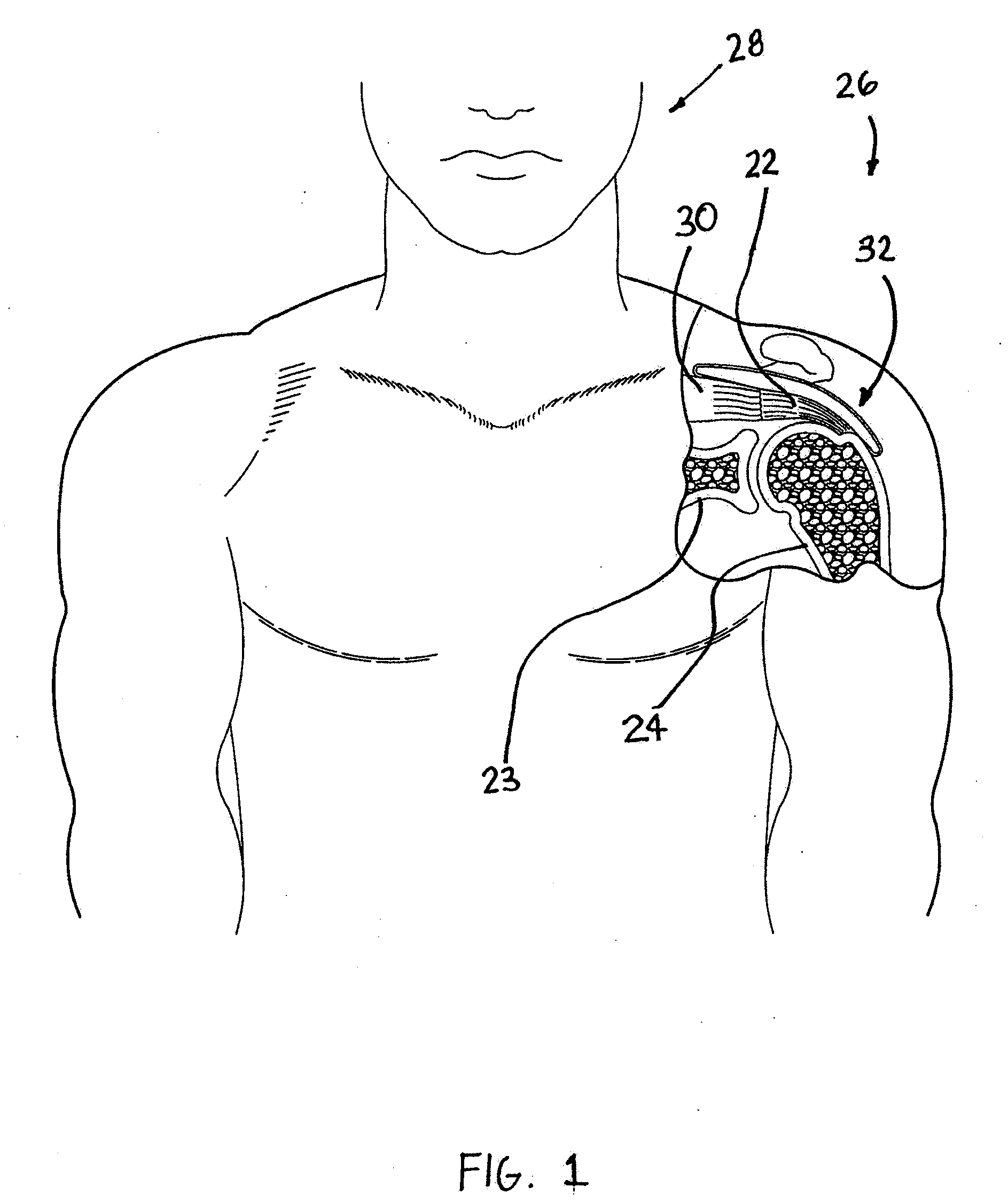
[0029]FIG. 1 is a stylized anterior view of a patient 28. For purposes of illustration, a shoulder 26 of patient 28 is shown in cross-section in FIG. 1. Shoulder 26 includes a humerus 24 and a scapula 23. The movement of humerus 24 relative to scapula 23 is controlled by a number of muscles including: the deltoid, the supraspinatus, the infraspinatus, the subscapularis, and the teres minor. For purposes of illustration, only the supraspinatus 30 is shown in FIG. 1. With reference to FIG. 1, it will be appreciated that a distal tendon 22 of the supraspinatus 30 meets humerus 24 at an insertion point 32.

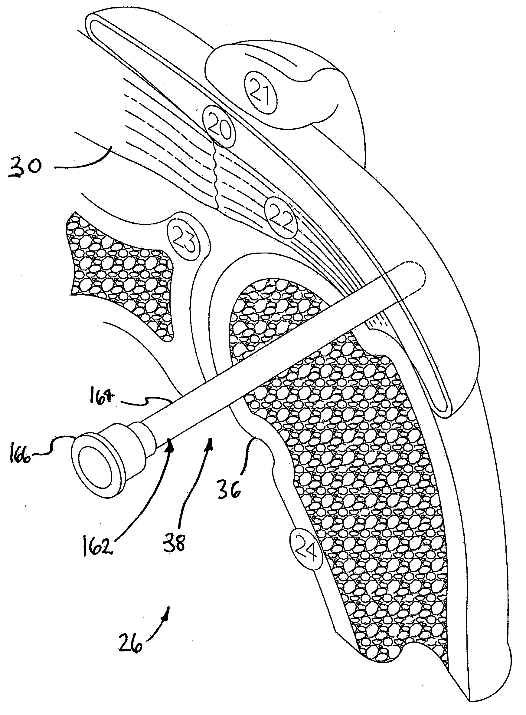
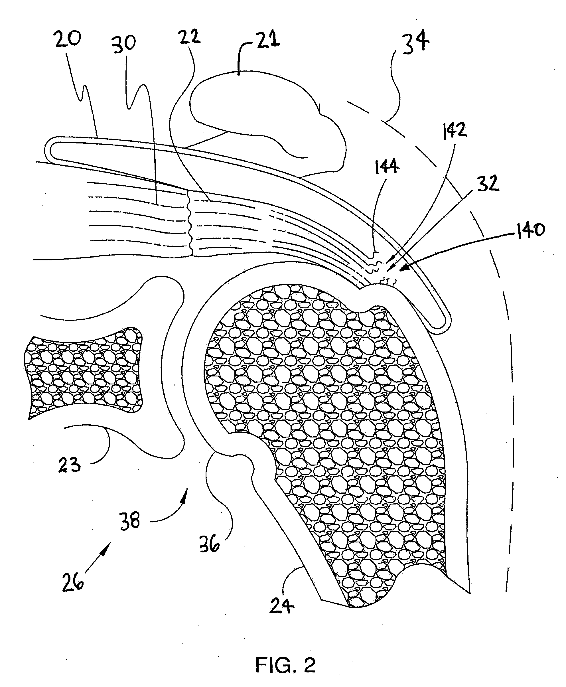
[0030]FIG. 2 is an enlarged cross sectional view of shoulder 26 shown in the previous figur...


PUM


Abstract

An implantable tendon protection system includes a body adapted to be implanted within a bursa overlying a tendon of a patient to protect the tendon. The body may be fixed to the tendon with adhesive, sutures, staples, and/or anchors. A surgical kit is provided with such a tendon protection system and an insertion cannula. Methods of protecting a tendon of a patient are also disclosed.

Description

CROSS-REFERENCE TO RELATED APPLICATIONS[0001]This application claims priority to U.S. Provisional Applications No. 61 / 143,267, filed Jan. 8, 2009, entitled “Methods and Apparatus for Treating Partially Torn Tendons”; and No. 61 / 153,592, filed Feb. 18, 2009, entitled “Implantable Tendon Protection System and Related Methods”; and No. 61 / 162,234, filed Mar. 30, 2009, entitled “Medical Device Delivery System and Method”; and No. 61 / 184,198, filed Jun. 4, 2009, entitled “System for Delivering and Fixing a Disk”; and No. 61 / 253,800, filed Oct. 21, 2009, entitled “System and Methods for Fixing Material to a Target Tissue”. Each patent application is incorporated herein by reference in its entirety.FIELD OF THE INVENTION[0002]The present invention relates generally to orthopedic medicine and surgery. More particularly, the present invention relates to methods and apparatus for treating articulating joints.BACKGROUND OF THE INVENTION[0003]Injuries to soft tissue, including, for example, mus...

Claims


Application Information

Patent Timeline
IPC IPC(8): A61F2/08
CPCA61F2/0063A61F2/0805A61F2/08A61F2002/0072A61F2/0077A61F2002/0086
Inventor EUTENEUER, CHARLES L.HEKTNER, THOMAS R.WESTLING, THOMAS A.MCCARVILLE, REBECCAFRION, DUANE
Owner ROTATION MEDICAL
Why Eureka
Try Eureka