Bioresorbable implant composition

Pending Publication Date: 2009-03-26
CASE WESTERN RESERVE UNIV
View PDF19 Cites 45 Cited by
  • Summary
  • Abstract
  • Description
  • Claims
  • Application Information

AI Technical Summary

Benefits of technology

[0002]The present invention generally relates to tissue engineering, and more particularly relates to a biores

Problems solved by technology
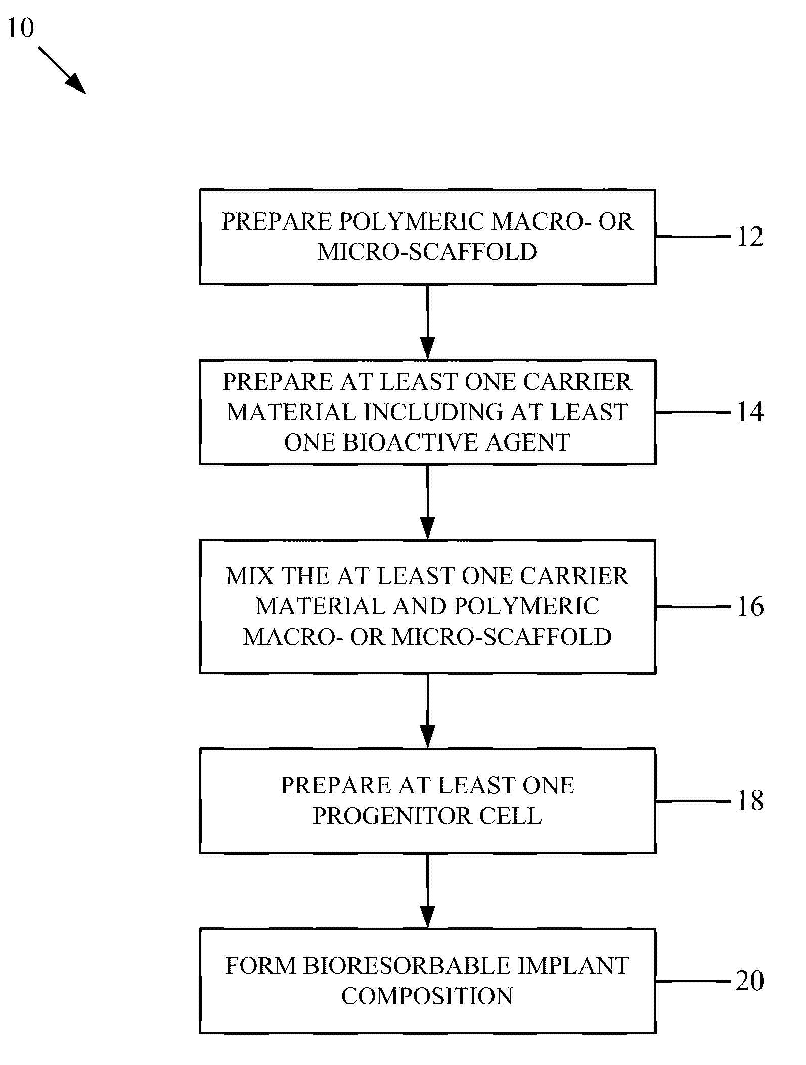
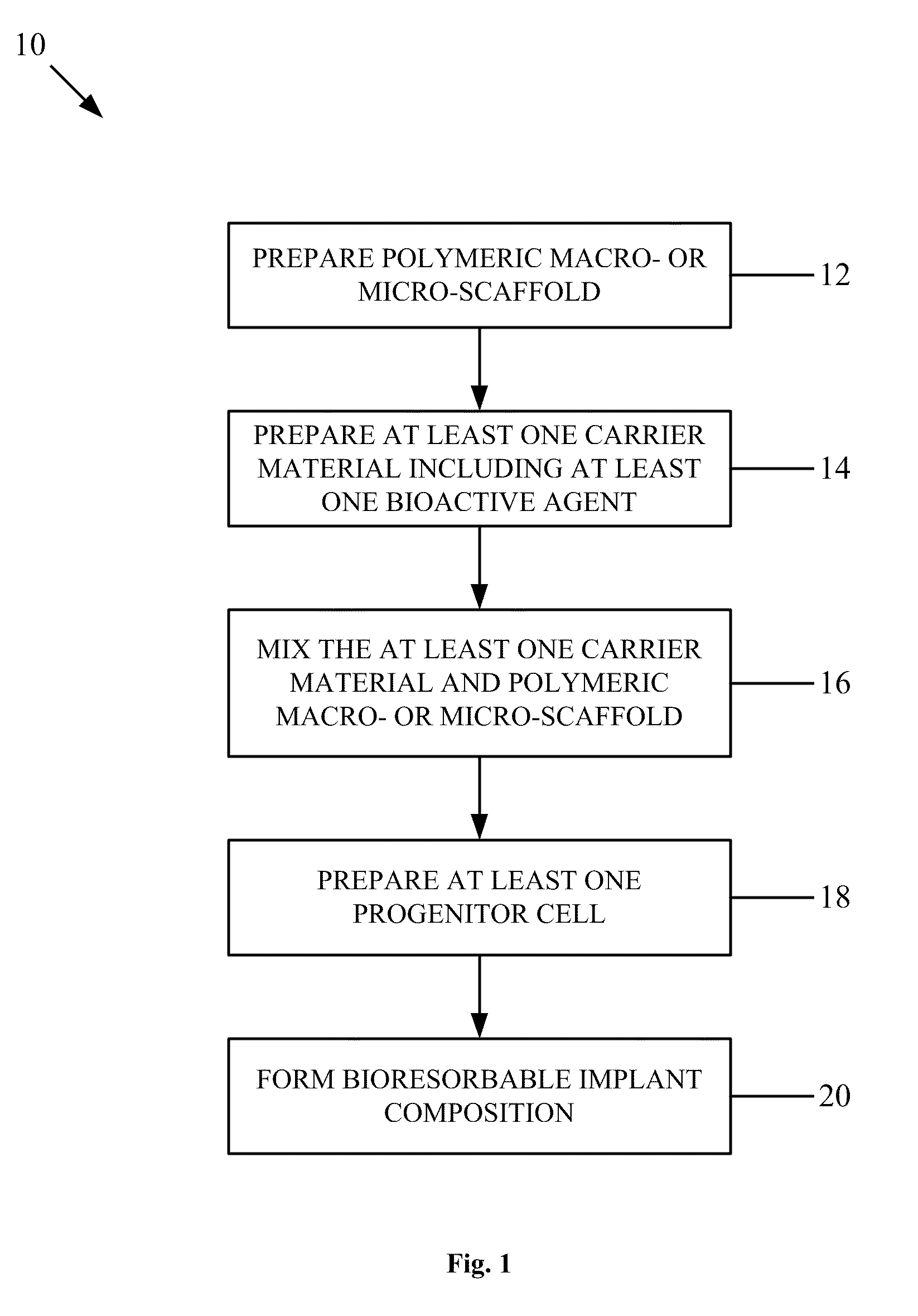
Articular cartilage has inadequate intrinsic ability to repair itself when damaged through injury or degenerative joint disease.
Current methods to address this problem have been met with limited success.
Subchondral bone marrow stimulation techniques, such as abrasion arthroplasty, subchondral drilling, and microfracture often result in the formation of fibrocartilage.
Osteochondral, periosteal, and perichondral autog

Method used


Image

  • Bioresorbable implant composition
  • Bioresorbable implant composition
  • Bioresorbable implant composition

Examples


example 1

Alginate Preparation

[0102]Sodium alginate powder (FMC Biopolymers, Princeton, N.J.) was lyophilized until dry, purified by dialysis for 4 days, subjected to activated charcoal treatment, and then sterilized through a 0.22 μm filter. Some of the alginate was subjected to gamma irradiation at 5 MRad (Phoenix Lab, University of Michigan, Ann Arbor). The molecular weight was found to be 37,000 g / mol for irradiated alginate, and 121,000 g / mol for non-irradiated alginate as determined by SEC-MALS (FMC Biopolymers). A polypeptide having the amino acid sequence of SEQ ID NO: 1 (Commonwealth Biotechnologies, Richmond, Va.) was covalently coupled to the irradiated alginate as described by Luo D. et al., Nat. Biotechnol., 18(1):33-37 (2000). The plasmid pcDNA3.1 / Hygro / lacZ was obtained from Invitrogen (Carlsbad, Calif.). MC3T3-E1 Subclone 4 (ATCC #CRL-2593) cells were obtained from American Type Culture Collection (Manassas, Va.). Phosphate buffered saline (PBS) and (α-MEM were obtained from H...

example 2

Preparation and Characterization of Calcium-Phosphate DNA Nanoparticles

[0103]Two types of Calcium-Phosphate DNA Nanoparticles were fabricated: calcium phosphate core with DNA coating, and calcium phosphate-DNA core with BSA coating. CaP core-DNA coated particles were created by a slight modification to the previously described method of Sokolova, V. V. et al., Biomaterials, 27(16):3147-3153 (2006). Equal volumes of 18.7 mM CaCl2 (pH 9) and 11.23 mM Na2HPO4 (pH 9) were added simultaneously to a tube with a magnetic stir bar. The solution was mixed for 30 seconds and 200 μg of DNA was added to quench the crystallization by coating the crystals. CaP-DNA core / BSA coated particles were created by a modification of the method described by Li, Y et al., Int J Pharm., 269(1):61-70 (2004). 120 μg DNA was mixed with 100 μl 2 M CaCl2. This solution was added drop-wise to 1 ml of 2×HBS (pH 7) while stirring. Then, 780 μl of distilled water was immediately added. The mixture was stirred at room ...

example 3

In vitro Cell Transfection Using Calcium-Phosphate DNA Nanoparticles

[0106]CaP core-DNA coated and CaP-DNA core-BSA coated NPs were freshly prepared using DNA encoding for lacZ. MC3T3-E1 cells were seeded the day before transfection. For transfection, the cells were rinsed once with PBS, followed by the addition of serum-free media containing 10% v / v of NPs. The cells were incubated for 5 hours at 37° C., and then the media was removed and replaced with complete medium (α-MEM+10% FBS). 48 hours post-transfection, the cells were rinsed with PBS, fixed with 0.2% glutaraldehyde, and stained with X-Gal to assay lacZ expression. 24 hours after staining, the cells were rinsed with PBS and examined under the microscope to determine transfection efficiency.


PUM

PropertyMeasurementUnit
Biodegradabilityaaaaaaaaaa
Bioabsorbableaaaaaaaaaa
Bioactiveaaaaaaaaaa

Abstract

A bioresorbable implant composition includes a polymeric macro- or micro-scaffold and first and second bioactive agents respectively incorporated on or within the polymeric macro- or micro-scaffold. The first and second bioactive agents modulate a different function and/or characteristic of a cell.

Description

RELATED APPLICATION[0001]This application claims priority from U.S. Provisional Application No. 60 / 955,523, filed Aug. 13, 2007, the subject matter, which is incorporated herein by reference.TECHNICAL FIELD[0002]The present invention generally relates to tissue engineering, and more particularly relates to a bioresorbable implant composition and method for promoting tissue growth (e.g., bone and / or cartilage) in a subject.BACKGROUND OF THE INVENTION[0003]Articular cartilage has inadequate intrinsic ability to repair itself when damaged through injury or degenerative joint disease. Current methods to address this problem have been met with limited success. Subchondral bone marrow stimulation techniques, such as abrasion arthroplasty, subchondral drilling, and microfracture often result in the formation of fibrocartilage. Osteochondral, periosteal, and perichondral autografts utilized to treat cartilage defects can be complicated by problems associated with donor-site morbidity, limit...

Claims


Application Information

Patent Timeline
IPC IPC(8): A61F2/02A61K35/00A61K47/36A61K38/18A61K31/7088A61K31/7105
CPCA61K9/0024A61K31/7088A61K38/30A61K38/1875A61K38/1841A61K38/1825C12N2533/74C12N2510/00C12N15/87A61K31/7105A61K47/36A61L27/3834A61L27/54A61L2300/258A61L2300/414A61L2300/45A61L2300/602A61L2300/64A61K2300/00
Inventor ALSBERG, EBENCAPLAN, ARNOLD I.
Owner CASE WESTERN RESERVE UNIV
Why Eureka
Try Eureka