Load sensitive snow barrier device

Inactive Publication Date: 2010-08-05
ROOFERS WORLD
View PDF24 Cites 13 Cited by
  • Summary
  • Abstract
  • Description
  • Claims
  • Application Information

AI Technical Summary

Benefits of technology

[0011]The present invention keeps snow from sliding off a roof during regular snow conditions, while allowing excessive snow to safely slide off once a given snow load threshold is reached in order to prevent catastrophic damage to the roof.
[0017]In another aspect of the present invention, there is provided a method of protecting a roof from damage due to excessive snow accumulation, comprising placing a plurality of the snow-retaining devices described herein on the roof.

Problems solved by technology

Nonetheless, the devices serve to maintain snow loads on the roof itself, thereby contributing to the roof caving in or causing undue stress to the roof when the snow load is excessive.
In addition, the openings of the flat blade are not designed to allow for the flow of solids such as snow or ice.
Consequently, the snow stop cannot effectively reduce the snow load on a roof in order to prevent a roof from caving in.
However, there are a number of drawbacks generally associated with these snow guards.
In particular, the securing means to attach flags to the pipes do not entirely prevent rotation of the flags when subjected to disturbances such as wind gusts.
In addition, the securing means are expensive to manufacture and difficult to install.
Furthermore, while the device may haphazardly permit a small portion of the snow load to fall from the roof, it is not designed to fail under the weight of dangerous snow load.
This device, for use with metal roofs only, is designed to prevent roof damage at the point of attachment only, and does not prevent the dangerous accumulation of snow on the entire metal roof.
None of the cited prior art disclose a snow barrier having a load sensitive mechanism to prevent large snow deposits from damaging roofs or even causing them to cave in.

Method used


Image

  • Load sensitive snow barrier device
  • Load sensitive snow barrier device
  • Load sensitive snow barrier device

Examples


Embodiment Construction

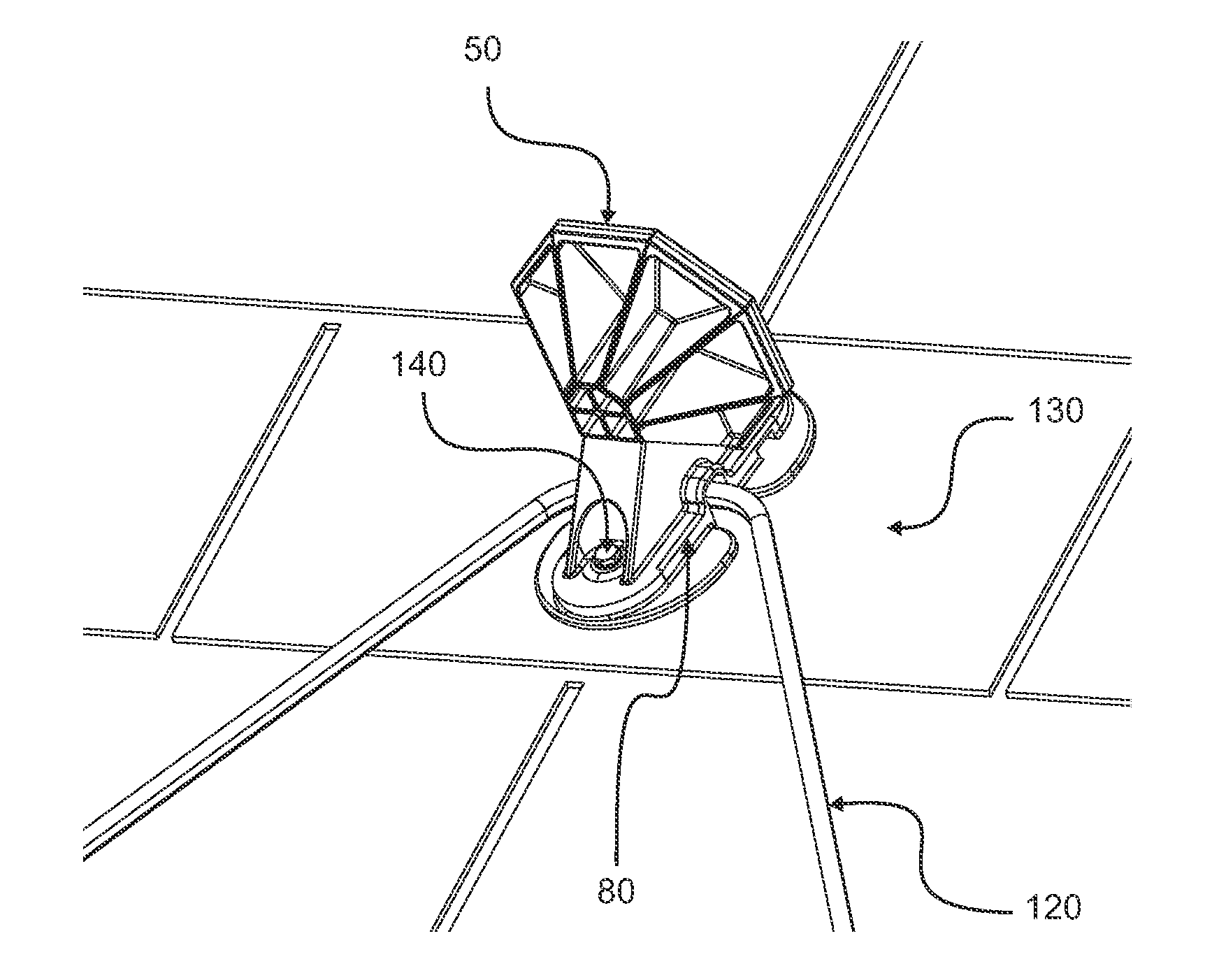
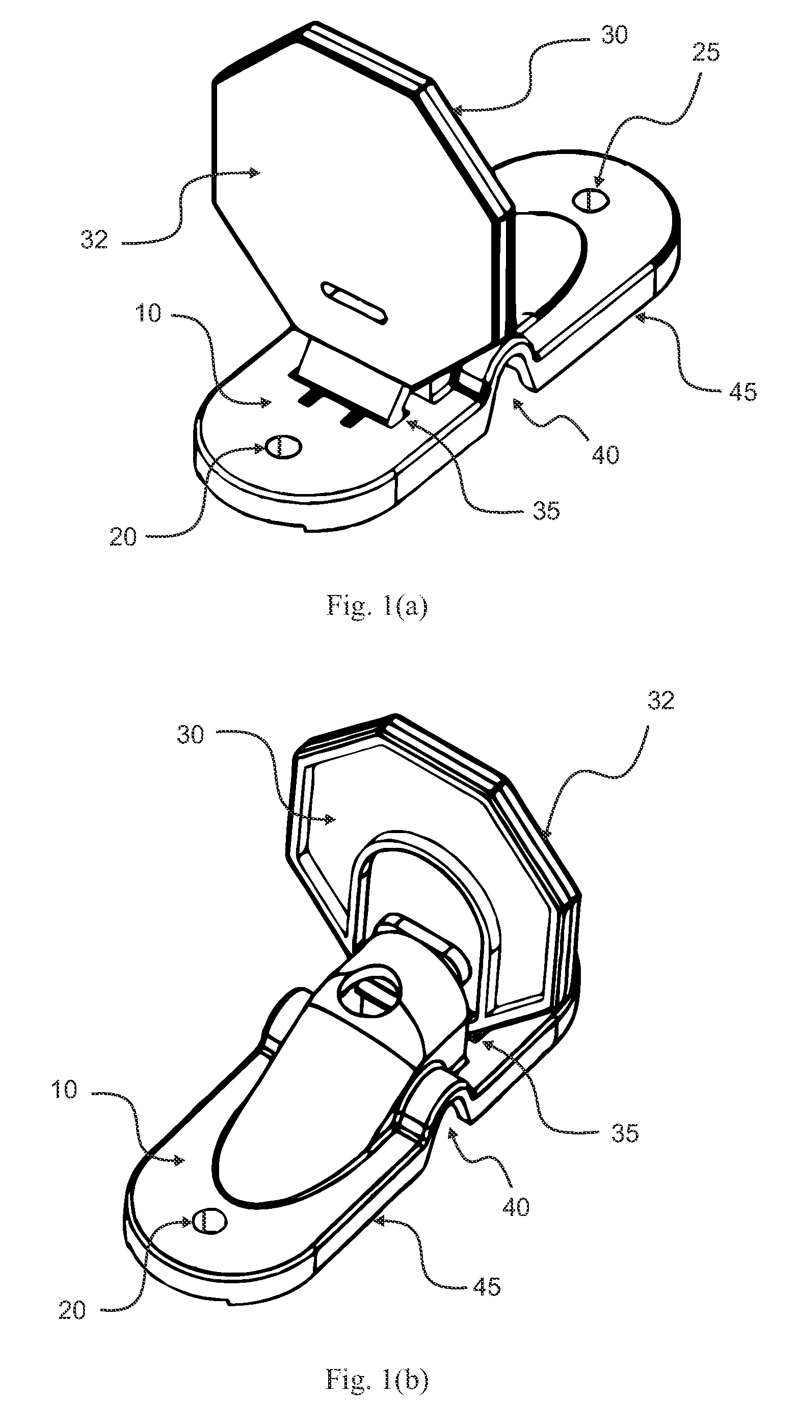
[0027]General features of the present invention are shown in FIGS. 1(a) and 1(b). The base anchor (10), which may be made of a polycarbonate material, is attached to a roof using bolts or screws that are inserted through holes (20) and (25). Base anchor (10) optionally includes a base surface (45) that serves as a waterproof seal. The upper member (30) is removably attached to the base anchor (10) at an attachment assembly junction (35). The upper member (30) may also be made of polycarbonate material.

[0028]As illustrated, upper member (30) preferably has a generally flat face (32), that may be of any shape. The illustrated shape is generally octagonal. Other contemplated geometrical shapes for the flat face (32) of upper member (30) are depicted in FIG. 8. Further shapes for the flat face (32) of upper member (30) are contemplated (not shown), and include shapes with or without holes, screens and other barrier shapes. Such shapes may also be of recognizable silhouettes including an...


PUM


Abstract

A snow-retaining device comprises a detachable upper member attached to a base anchor. The base anchor is adapted to be coupled to a roof. The upper member prevents snow from sliding off the roof during regular snow conditions. In order to prevent catastrophic damage to the roof, if a snow load on the roof exceeds a maximum threshold, the upper member detaches from the base anchor to allow some or all of the snow to slide off the roof. The device optionally integrates a snow melting device.

Description

CROSS REFERENCE TO RELATED APPLICATIONS[0001]This application claims the benefit of U.S. Provisional Patent Application No. 61 / 148,903 filed on Jan. 30, 2009 which is hereby incorporated by reference in its entirety.FIELD OF THE INVENTION[0002]The present invention relates generally to snow barriers or guards that are coupled to a roof to inhibit the sliding of accumulated snow from the roof up to a pre-determined load, thereby preventing damage to the roof due to excessive accumulation of snow.BACKGROUND[0003]It is well known in the art to apply brackets, stops, or fences to a roof in order to prevent snow that has accumulated upon the roof from sliding from the roof. These devices help to keep snow from damaging eavestroughs, landscaping on the ground below, etc., or falling dangerously onto pedestrians or vehicles. Nonetheless, the devices serve to maintain snow loads on the roof itself, thereby contributing to the roof caving in or causing undue stress to the roof when the snow ...

Claims


Application Information

Patent Timeline
IPC IPC(8): E04B1/92E04D13/10
CPCE04D13/106E04D13/103
Inventor ELLIOTT, CRAIGPELL, GABRIELLEHASZCZYN, CAMNELSON, ROBINYAO, HAN
Owner ROOFERS WORLD
Why Eureka
Try Eureka