Non-rotational stabilization of the flame of a premixing burner

a burner and flame stabilization technology, which is applied in the direction of machines/engines, combustion types, lighting and heating apparatus, etc., can solve the problems of general undesirable combustion oscillation, combustion oscillation, damage to the entire combustion system, etc., and achieve the effect of stabilizing the burner and reliably stabilizing the combustion reaction of the spray

Inactive Publication Date: 2010-08-05
SIEMENS AG
View PDF13 Cites 33 Cited by
  • Summary
  • Abstract
  • Description
  • Claims
  • Application Information

AI Technical Summary

Benefits of technology

[0010]One advantage of the present invention is that complex swirling of the air / fuel mixture is not necessary, the air and fuel being thoroughly mixed by vorticity. Recirculation also causes the air / fuel mixture to be mixed with the hot combustion gas resulting during combustion. This stabilizes the burner as continuous ignition is thus achieved.
[0011]Fuel or an air / fuel mixture can be injected into the reaction chamber as pilot fuel for flame stabilization purposes. In this process the pilot fuel can be injected into the reaction chamber with a parallel or anti-parallel offset in respect of the air / fuel mixture. If the pilot fuel is injected into the reaction chamber with an anti-parallel offset in respect of the air / fuel mixture, the hot gases of the pilot flame are available to the premixing sprays for the hot gas intake. This reliably stabilizes the combustion reaction of the sprays. Since the hot gases also exit from the combustion chamber counter to the premixing spray direction, practically all the hot gas is available to ignite and stabilize the premixing sprays.
[0012]The air / fuel mixture can preferably be formed by injecting the fuel into an oxidation means in a premixing spray nozzle at a speed that is higher than that of the oxidation means. In particular the fuel can be injected into the oxidation means parallel to the flow direction of said oxidation means. Air, i.e. the oxygen in the air, can in particular serve as the oxidation means.
[0013]The side of the reaction chamber on which the pilot burner is located can also be cooled using an oxidation means, which is then fed to the pilot fuel during injection into the reaction chamber. The oxidation means can be air for example.
[0014]The major pressure loss in the premixing spray nozzles means that a large pressure difference is available for such cooling of the points that are subject to significant heat loading on the side of the combustion chamber where the pilot burner is located. This allows the application of different cooling technologies, such as impact spray cooling, impact spray cooling with surface enlargement or fin cooling. Dimple, longitudinal and transverse fins can be used for example for impact spray cooling with surface enlargement. Open combustion chamber cooling is then not required.
[0015]The inventive method, in particular the principle of anti-parallel injection of pilot fuel and air / fuel mixture described above, can be used both for tubular combustion chamber systems and annular combustion chamber systems. The pilot burner used here can be a rotationally stabilized burner or a spray burner.

Problems solved by technology

Combustion oscillations are generally undesirable, as they have a negative effect on combustion and can damage the entire combustion system.
This can cause combustion oscillations.
No system or method, with which combustion oscillations are completely avoided, is known to date.
However all these systems are characterized in that they produce a clearly defined and spatially limited flame.
Therefore combustion oscillations or flame instabilities also inevitably occur here at certain operating points.

Method used


Image

  • Non-rotational stabilization of the flame of a premixing burner
  • Non-rotational stabilization of the flame of a premixing burner
  • Non-rotational stabilization of the flame of a premixing burner

Examples


Embodiment Construction

[0038]The first exemplary embodiment of the present invention is described below with reference to FIGS. 1 to 4.

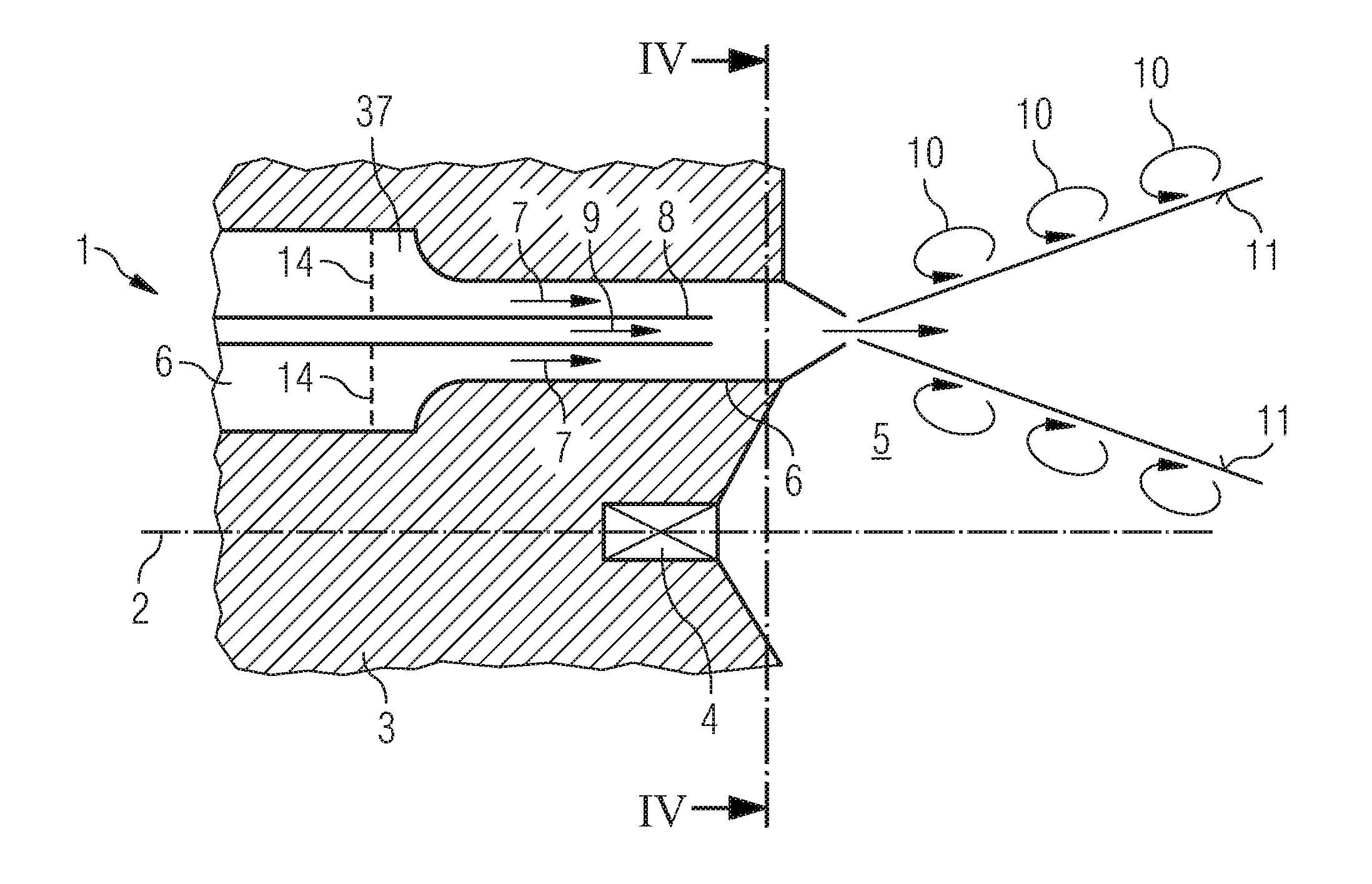
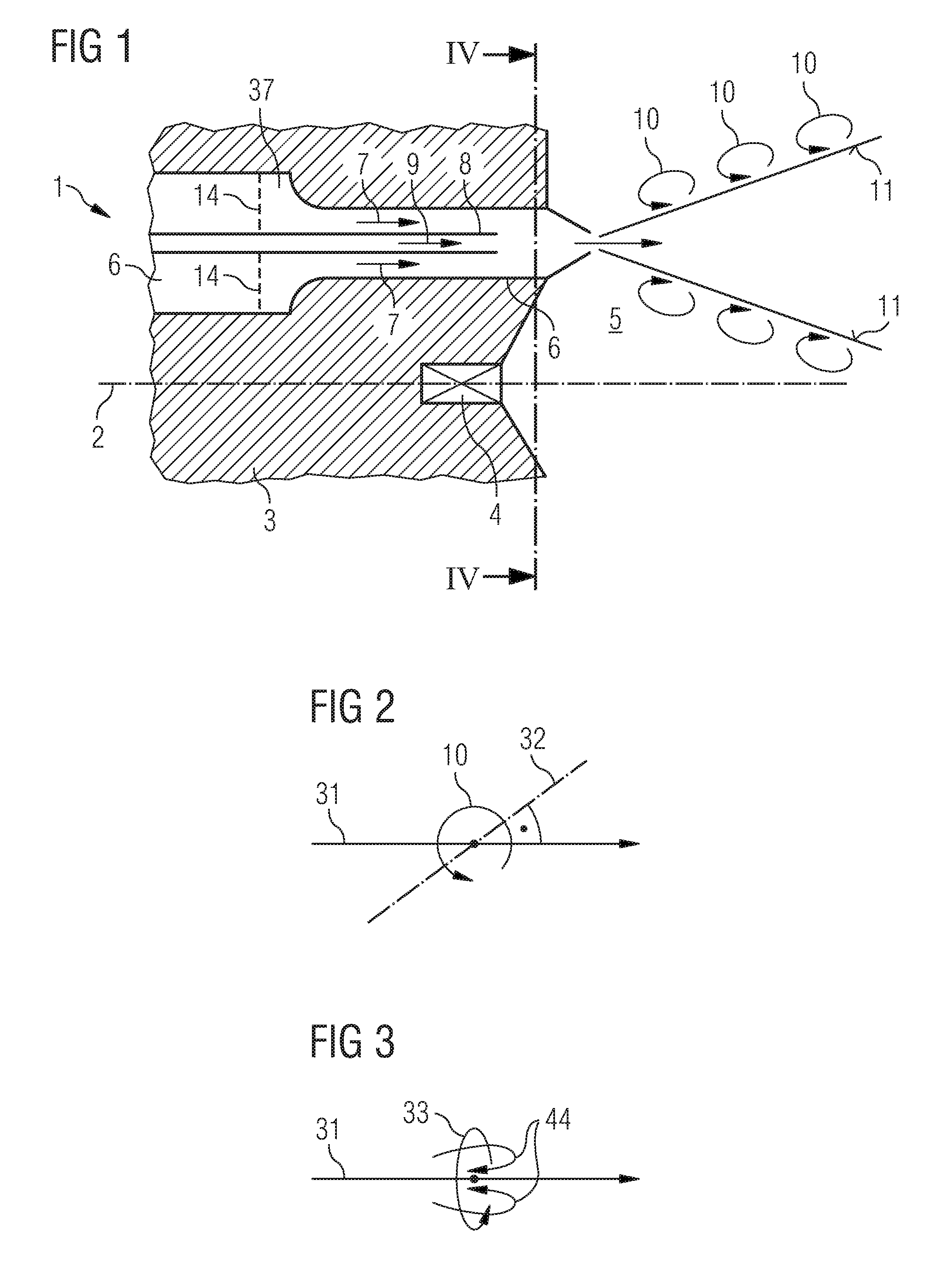
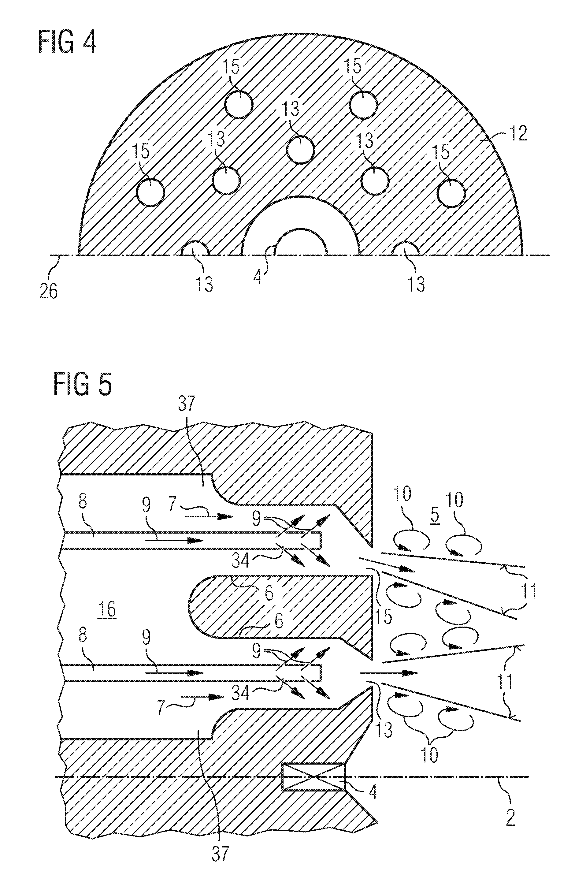
[0039]FIG. 1 shows a schematic diagram of the cross-section through a part of the rear wall of a largely rotationally symmetrical premixing burner 1. The center line 2 shows the axis of symmetry of the premixing burner 1. The premixing burner 1 comprises a housing 3, a pilot burner 4, a reaction chamber 5 and a premixing spray nozzle 6. The premixing spray nozzle 6 has an inlet opening 13, which opens into the reaction chamber 5. The pilot burner 4, which in the present exemplary embodiment is a rotationally stabilized burner, is located in the center of the rear wall of the premixing burner 1. It is concentrically surrounded by a number of premixing spray nozzles 6, which are likewise located on the rear wall of the premixing burner 1.

[0040]The premixing spray nozzle 6 contains a fuel nozzle 8, which is surrounded by an air inlet channel 37. The air inlet channel 37 and t...


PUM


Abstract

A method for stabilizing the flame of a premixing burner, comprising a reaction chamber containing a fluid is provided. The method includes injecting an air-fuel mixture into the reaction chamber at a speed that is different from that of the fluid present in the reaction chamber, adjusting the speed such that vortices form at the boundary between the air-fuel mixture and the surrounding fluid. A premixing burner including a reaction chamber and at least one premixing spray nozzle opening into the reaction chamber is also provided. The premixing burner injects an air-fuel mixture into the reaction chamber at a speed that is different from that of the surrounding fluid, the speed being adjusted such that vortices from at the boundary between the air-fuel mixture and the surrounding fluid.

Description

CROSS REFERENCE TO RELATED APPLICATIONS[0001]This application is the US National Stage of International Application No. PCT / EP2008 / 057757, filed Jun. 19, 2008 and claims the benefit thereof. The International Application claims the benefits of European Patent Office application No. 07012207.2 EP filed Jun. 21, 2007, both of the applications are incorporated by reference herein in their entirety.FIELD OF INVENTION[0002]The present invention relates to a method for stabilizing the flame of a premixing burner.BACKGROUND OF INVENTION[0003]Combustion oscillations can occur during the combustion of fuel or an air / fuel mixture in combustion chambers of gas turbines. Such oscillations are characterized by greatly increased pressure amplitudes at different frequencies. Combustion oscillations can occur in the combustion chamber itself as well as in the adjacent components of the gas turbine and can be measured there. Combustion oscillations are generally undesirable, as they have a negative ...

Claims


Application Information

Patent Timeline
Patent Type & Authority Applications(United States)
IPC IPC(8): F23D14/02F23R3/18F23D11/10F23R3/28
CPCF23C9/006F23C2202/40F23D11/102F23D14/02F23R2900/03282F23R3/26F23R2900/00013F23R2900/00014F23D2203/007
Inventor CANO WOLFF, MARIANOFLOHR, PATRICK RONALDHASE, MATTHIASLENZE, MARTINMEISL, JURGENPIXNER, PAULREMLINGER, UWESCHILDMACHE, KAI-UWESCHNEIDER, THOMAS ALEXISVAN KAMPEN, JAAP
Owner SIEMENS AG
Why Eureka
Try Eureka