Method for the secured release of an electromechanically actuable parking brake

a technology of electromechanical action and secured release, which is applied in the direction of mechanical equipment, braking systems, transportation and packaging, etc., to achieve the effect of eliminating the risk of overheating the brak

Inactive Publication Date: 2010-08-05
CONTINENTAL TEVES AG & CO OHG
View PDF6 Cites 16 Cited by
  • Summary
  • Abstract
  • Description
  • Claims
  • Application Information

AI Technical Summary

Benefits of technology

[0007]An object of the present invention is therefore to disclose a method for the secured release of an electro...

Problems solved by technology

However, the specified publication does not contain any indications of how an optimum distance, at which there is no ...

Method used


Image

  • Method for the secured release of an electromechanically actuable parking brake
  • Method for the secured release of an electromechanically actuable parking brake
  • Method for the secured release of an electromechanically actuable parking brake

Examples


Embodiment Construction

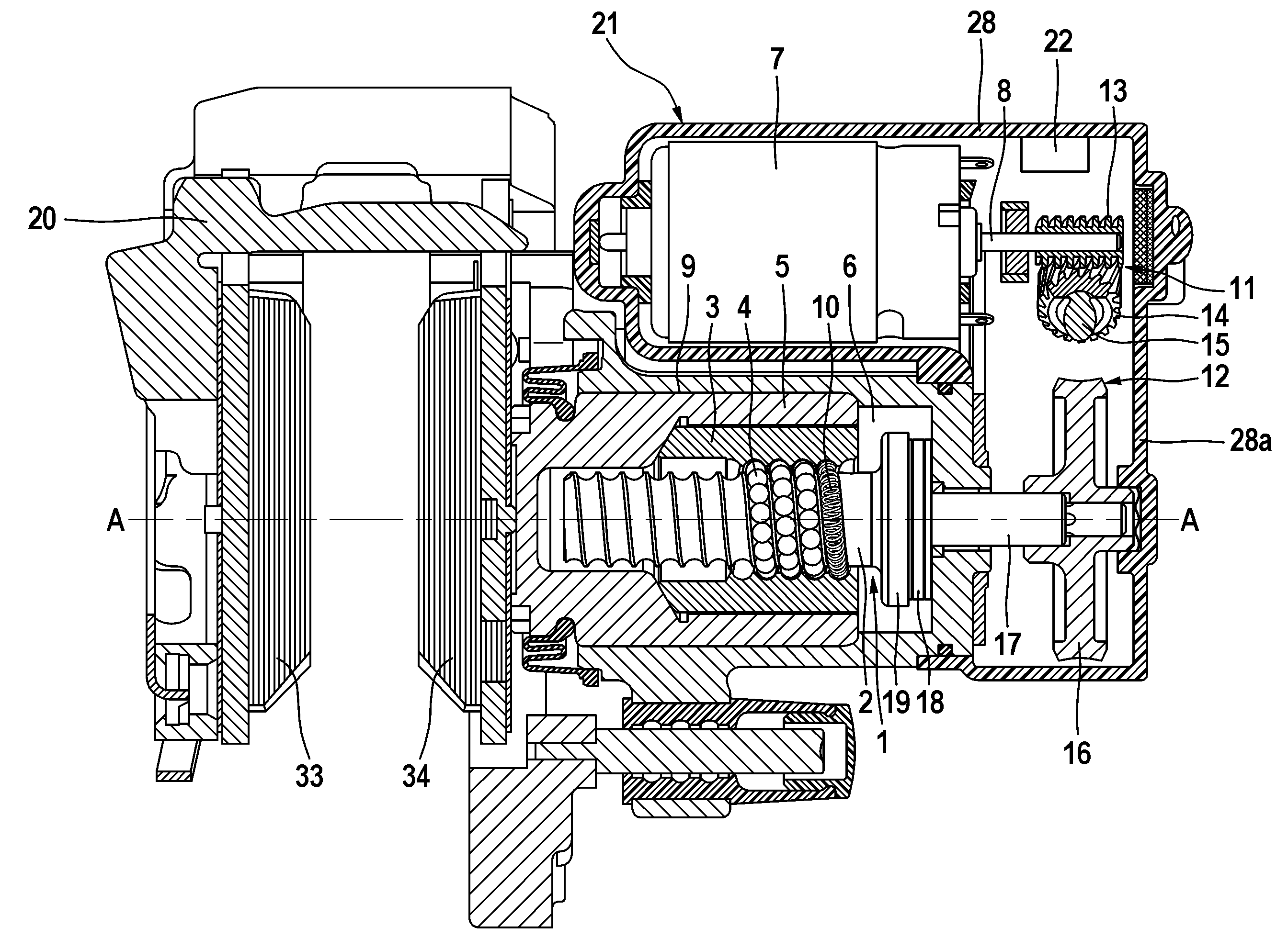
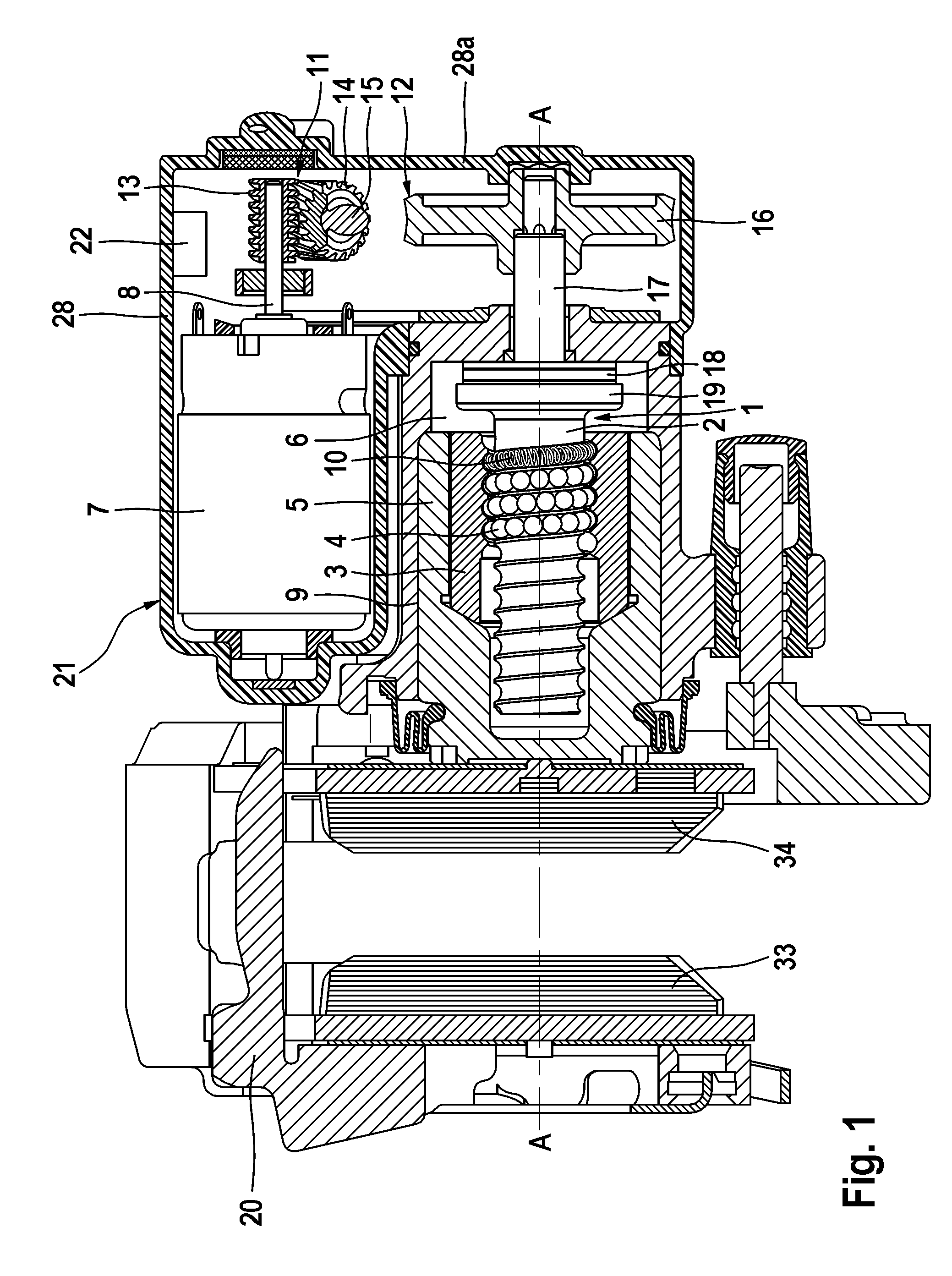
[0023]The inventive hydraulic vehicle brake which is illustrated in FIG. 1 has, on the one hand, a hydraulically actuable service brake and, on the other hand, an electromechanically actuable parking brake. The vehicle brake is embodied in the example shown as a floating calliper disc brake, the function of which is caused by a hydraulic actuation and is well known to a person skilled in the art in this field, and for this reason does not need to be explained in more detail. An electromechanical actuator or electric motor, which is integrated together with a two-stage transmission of the necessary sensor system and an electronic control unit 21 in a drive module 22, serves to actuate the parking brake. The abovementioned vehicle brake also has a brake housing and / or a brake calliper 20 which engages around the external edge of a brake disc (not illustrated), and two brake linings 33, 34 which are arranged on each side of the brake disc. The brake housing 20 forms, on its inner side,...


PUM


Abstract

A method to limit overheating of a brake equipped with an electromechanically actuable parking brake including the steps of: driving a threaded spindle by an electric motor until a power drain (Imax), corresponding to a brake application force (F), is reached; detection of a travel distance (x0) of the piston corresponding to the brake application force (F) of the brake caliper in a locked state; determination of a second travel distance (x1) by adding a further travel distance value (x11), which corresponds to the desired clearance value, to form (x0); driving of the electric motor until the second travel distance (x1) has been covered by the brake piston; and comparing the vehicle speed with a predefined first speed value, at the upward transgression of which the electric motor is driven once more in the release direction until a further, previously defined travel distance (x12) has been covered.

Description

CROSS REFERENCE TO RELATED APPLICATIONS[0001]This application is the U.S. national phase application of PCT International Application No. PCT / EP2008 / 061611, filed Sep. 3, 2008, which claims priority to German Patent Application No. 10 2008 018 749.6, filed Apr. 14, 2008, and German Patent Application No. 10 2007 043 555.1, filed Sep. 12, 2007, the contents of such applications being incorporated by reference herein.BACKGROUND OF THE INVENTION[0002]1. Field of the Invention[0003]The present invention relates to a method for the secured release of an electromechanically actuable parking brake which has a brake piston, which acts on a friction element and is displaceable into an actuation position in a brake calliper in which it presses the friction element against a brake disc, and a spindle / nut arrangement which is driven by an electric motor, is coaxial with respect to the central axis of the brake piston and has the purpose of mechanically locking the brake piston in the actuation ...

Claims


Application Information

Patent Timeline
IPC IPC(8): F16D65/14F16D65/18
CPCB60T7/108B60T13/746F16D65/18F16D2125/52F16D2125/40F16D2125/48F16D2121/24
Inventor SCHUMANN, MARCUSMARON, CHRISTOFVOLKEL, JURGEN
Owner CONTINENTAL TEVES AG & CO OHG
Why Eureka
Try Eureka