
Piston for a piston-cylinder arrangement and production method

a technology of piston cylinder and piston cylinder, which is applied in the direction of shock absorbers, braking systems, machines/engines, etc., can solve the problems of high corrugated sealing lip, poor fabrication precision, and poor sealing function

Active Publication Date: 2010-08-05
GKN SINTER METALS GMBH & CO KG
View PDF3 Cites 6 Cited by
  • Summary
  • Abstract
  • Description
  • Claims
  • Application Information

AI Technical Summary

Benefits of technology

[0011]The present invention provides a piston with a sealing lip that is uniformly developed in the circumferential direction. In other words, this means that the sealing lip is formed uniform or constant in the circumferential direction, i.e. independent of the angle circumference, or that it is axissymmetrical to the longitudinal axis of the piston or that it has a defined or specified profile in the longitudinal section. This can be achieved, for example, in that the sealing lip of the known pistons is finished in a suitable manner to obtain the desired form. Compared with known pistons, the proposed piston has an improved sealing function.
[0013]The sealing lip may protrude radially outward from the outer circumferential surface. As a result, this ensures contact between the sealing lip and the inner wall of the cylinder of the piston-cylinder arrangement without gaps to the extent possible. In addition, this will also compensate for any potentially present “back memory” of the sealing collar, which is also referred to as “memory effect.”

Problems solved by technology

This known piston and this known method have the disadvantage that the sealing lip is highly corrugated, because of the internal stresses that are formed as a result of manufacturing during the forming of the circular washer into the sealing collar, which can impair the sealing function.
This known piston and this known method have the disadvantage that due to the manufacturing, the sealing lips have a relatively poor fabrication precision, since the material of the guide ring can freely flow in the axial direction during the radial compression.

Method used


Image

  • Piston for a piston-cylinder arrangement and production method
  • Piston for a piston-cylinder arrangement and production method
  • Piston for a piston-cylinder arrangement and production method

Examples


first embodiment

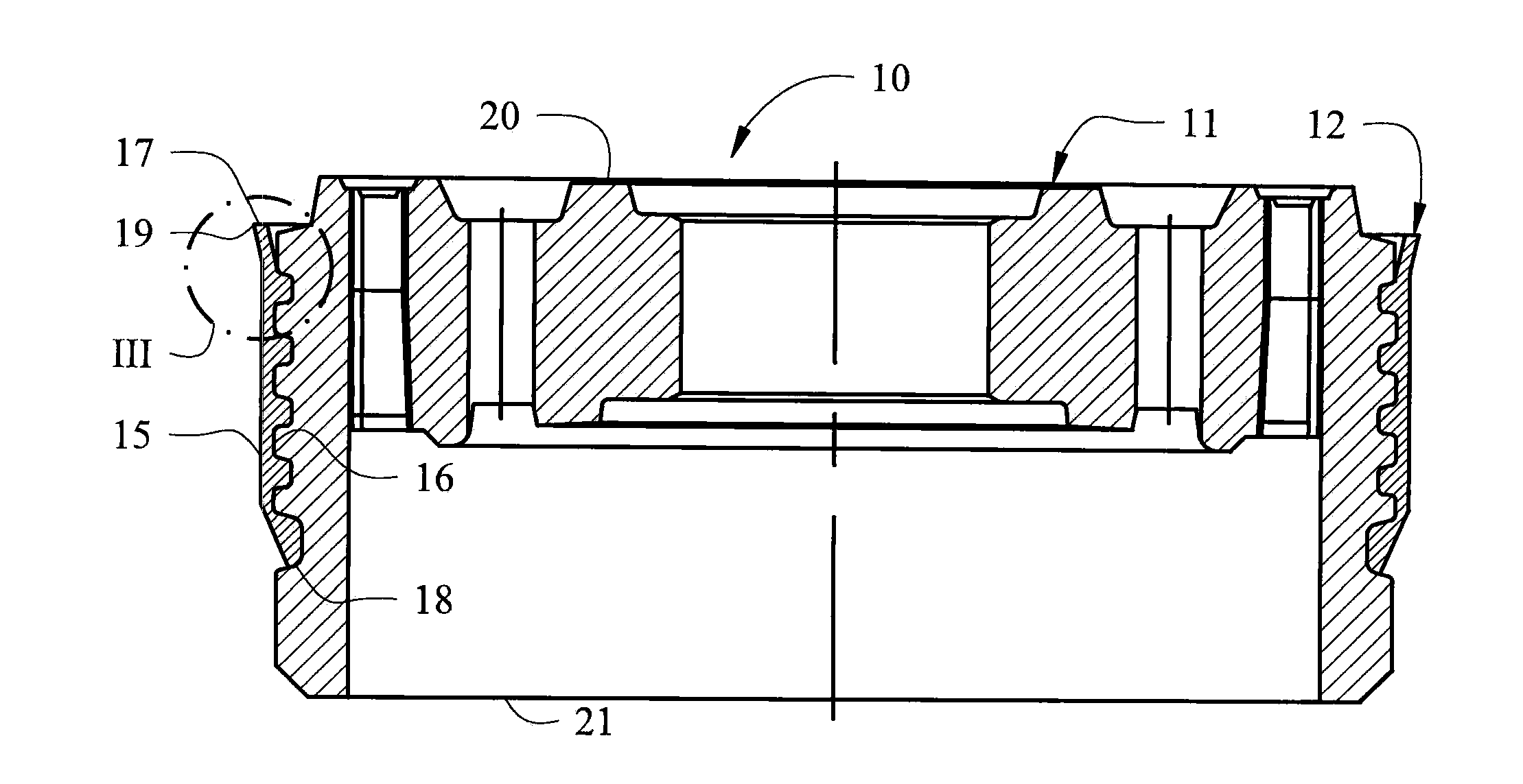
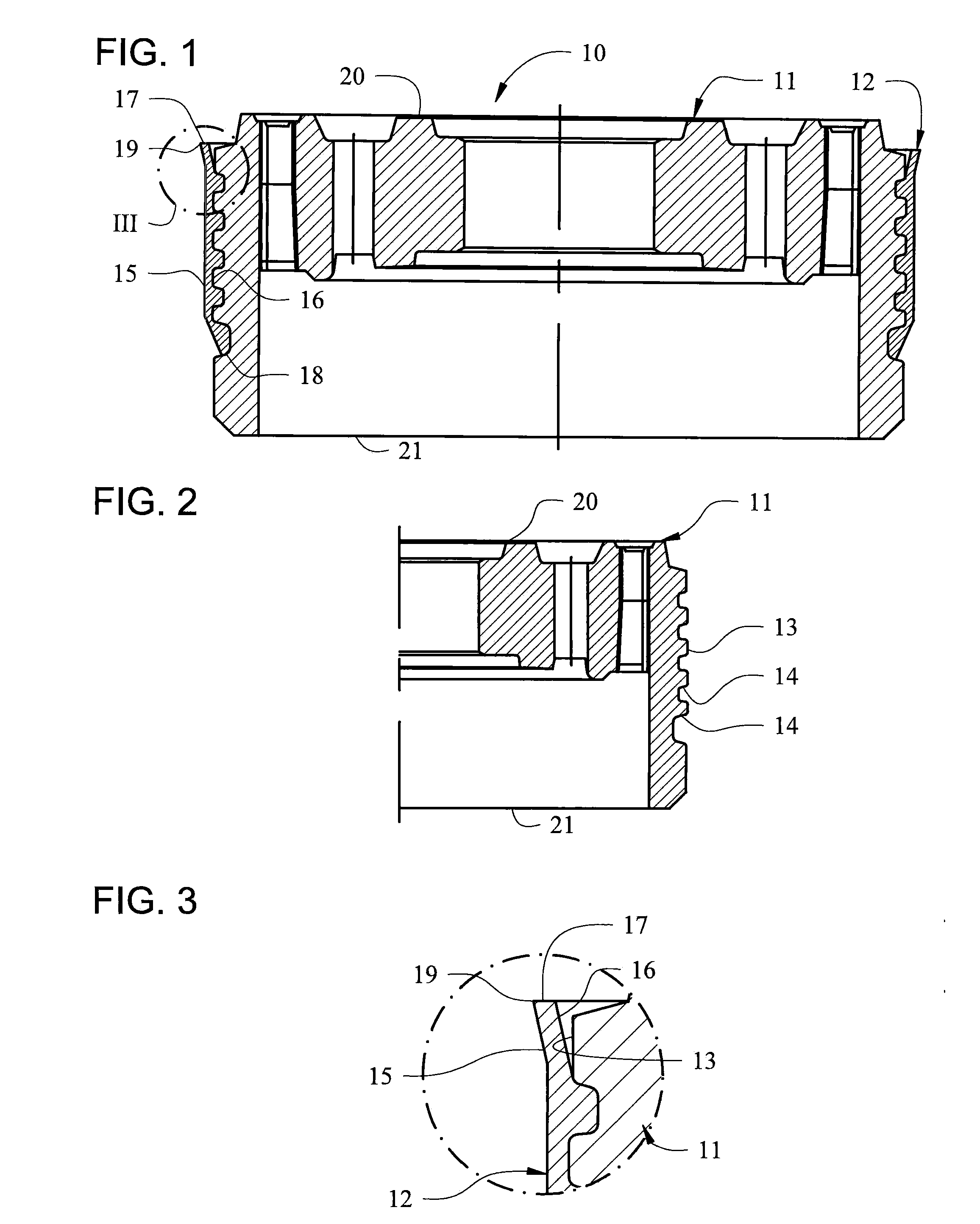
[0038]FIG. 1 represents a piston 10 in a first embodiment and is developed as a shock absorber piston. It has a piston body 11 and a sealing collar 12. The piston body 11 has a circumferential surface 13, in which five annular grooves 14 are developed, as can be easily seen in FIG. 2. The sealing collar 12 has an outer circumferential surface 15, an inner circumferential surface 16, a first peripheral surface 17, which is located at the top in FIG. 1, a second peripheral surface 18, which is at the bottom in FIG. 1, and a first sealing lip 19, which is shown enlarged in FIG. 3. The sealing collar 12 extends around the circumferential surface 13 and in the axial direction covers an upper part of this circumferential surface 13. In FIGS. 1 and 3, the first peripheral surface 17 connects the outer and inner circumferential surface 15, 16 with each other on the first upper end of the sealing collar 12 and delimits together with the outer circumferential surface 15 the first sealing lip ...

second embodiment

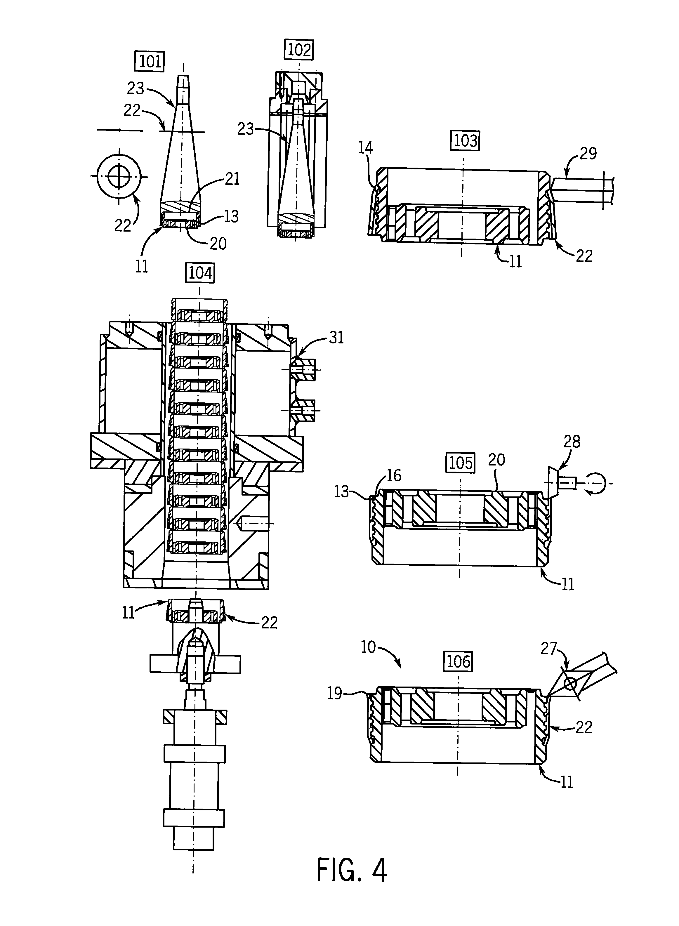
[0051]In a fifth step, which is illustrated in FIG. 9, on the one hand, the first and the second sealing lip 19, 26 are formed with the desired profile on the two cut off ends of the sealing blank 22, and on the other hand, the sealing blank 22 is widened on both of its ends. In this instance, this is performed by mechanical rotation with the help of two conical rolls 28, each of which are rotated about an axis which cuts the piston axis at a right angle, and which has a tapering conical cylindrical surface which extends radially away from the piston axis, thus to the left in FIG. 9, and are respectively pressed from above and below against the cut off first and second end, respectively, of the sealing blank 22, while the piston body 11 with the pressed on sealing blank 22 is rotated about the piston axis. Consequently, the two sealing lips 19, 26 were formed on the two ends of the sealing blank 22 and the piston 10 was finished in the

[0052]FIG. 10 illustrates a first sealing lip 19...


PUM

PropertyMeasurementUnit
obtuse angleaaaaaaaaaa
diameteraaaaaaaaaa
shapeaaaaaaaaaa

Abstract

The invention relates to a piston for a piston-cylinder arrangement, particularly a shock absorber piston, which includes a piston body, that has a circumferential surface. A sealing collar has an outer circumferential surface, an inner circumferential surface, a first peripheral surface, and a first sealing lip, and extends around the circumferential surface of the piston body and covers at least part of the circumferential surface in the axial direction. The first peripheral surface connects the two circumferential surfaces to each other at a first end of the sealing collar. The first sealing lip is delimited by the first peripheral surface and the outer circumferential surface, and the first sealing lip is configured evenly in the circumferential direction.

Description

CROSS-REFERENCE TO RELATED APPLICATIONS[0001]This is a continuation of International Patent Application No. PCT / EP2008 / 003127 filed Apr. 18, 2008, which claims priority of German Patent Application No. 10 2007 036 017.9-12 filed Jul. 30, 2007, the disclosures of which are hereby incorporated by reference in their entirety for all purposes.STATEMENT CONCERNING FEDERALLY SPONSORED RESEARCH OR DEVELOPMENT[0002]Not applicable.FIELD OF INVENTION[0003]The invention relates to a piston for a piston-cylinder arrangement, particularly a shock absorber piston, as well as a method for producing a piston, particularly such piston.BACKGROUND[0004]EP 1 121 544 B1 describes a piston for a piston-cylinder arrangement, particularly a shock absorber piston, which has a piston body with a circumferential surface and a sealing collar. The sealing collar has an outer circumferential surface, an inner circumferential surface, a first peripheral surface and a first sealing lip and extends around the circu...

Claims


Application Information

Patent Timeline
Patent Type & Authority Applications(United States)
IPC IPC(8): F16F9/36F16F9/32F16J9/20F16J1/00B23P15/10
CPCB23P15/10F16F9/368F16F2226/04Y10T29/49297Y10T29/49252Y10T29/49256Y10T29/49883Y10T29/49909Y10T29/49833
Inventor GRUBER, RAINERCASELLAS, ANTONIOSCHNEID, STEFAN
Owner GKN SINTER METALS GMBH & CO KG
Learn More